Control method of concentrated standby power automatic transfer system

A control method and self-switching technology, which is applied in the field of power transmission and distribution, can solve the problems of high cost, complicated cable connection, installation and debugging, etc., and achieve the effects of low equipment cost, simplified installation and debugging process, and reduced cable usage

Active Publication Date: 2010-05-19
JIANGSU DANYANG ELECTRIC POWER SUPPLY CORP +1
View PDF0 Cites 11 Cited by
  • Summary
  • Abstract
  • Description
  • Claims
  • Application Information

AI Technical Summary

Problems solved by technology

When multi-transformers are used for single-bus multi-section ring wiring power supply, it is necessary to use an independent sub-section backup self-injection device for every two bus sections, and install them on the sub-section switchgear. Both are cumbersome and costly

Method used


Image

  • Control method of concentrated standby power automatic transfer system
  • Control method of concentrated standby power automatic transfer system

Examples


Embodiment Construction

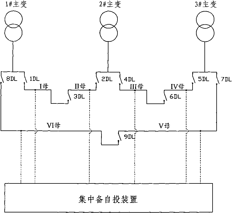
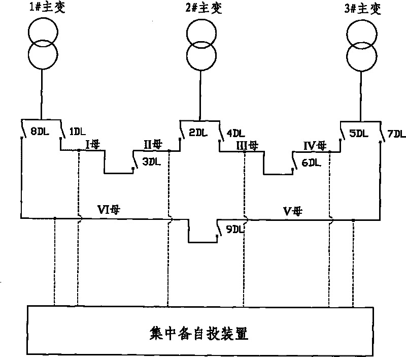
[0020] The embodiment shown in the figure includes a ring-connected power supply system with three main transformers and six sections on the low-voltage side. The system includes three main transformers: 1#main transformer, 2#main transformer, and 3#main transformer. The six bus sections from I bus to VI bus and the nine circuit breakers from 1DL to 9DL. The voltage detection signals of each bus section are connected to a centralized backup automatic switching device. The centralized backup automatic switching device automatically controls the backup power supply of all buses. Invest in control. Its control includes the following situations:

[0021] Situation 1: Three main transformers are running at the same time, namely 1DL, 2DL combined, 3DL quantile, 4DL, 5DL combined, 6DL quantile, 7DL, 8DL combined, 9DL quantile.

[0022] 1.1 If the 1# main transformer trips, the I mother VI mother loses voltage at the same time, and the standby auto-switching trips 1DL and 8DL at the same ...


PUM


Abstract

The invention belongs to the technical field of power transmission and distribution and relates to a control method of a concentrated standby power automatic transfer system. In the method, annular connection power supply systems of three main transformers and six subsections of low pressure side buses are provided, and the system comprises three main transformers 1-3# and also comprises six sections of buses I-VI and nine breakers 1DL-9DL. A voltage detection signal of each bus is connected to a concentrated standby power automatic transfer device, and the concentrated automatic transfer device controls the standby power automatic transfer of all buses. The invention has convenient installation and debugging and low equipment cost. The number of the buses subjected to capacity increment is increased through adding plug-in units during system capacity increment, thereby enhancing the expansibility of the device and reducing the workload of installation and debugging; and the concentrated standby power automatic transfer device can be conveniently installed on a bus observe and control screen, thereby effectively reducing the usage amount of cables and simplifying the installation and debugging process.

Description

Technical field [0001] The invention belongs to the technical field of power transmission and distribution, and relates to a control method of a centralized backup automatic switching system. Background technique [0002] In the traditional backup automatic switching system, two main circuit breakers connected to each two bus sections and a section circuit breaker connected between the two bus sections need to be equipped with a backup automatic switching device to automatically backup the power supply of the two bus sections. Invest. The basic operation process is: under normal conditions, two main circuit breakers are closed, one section circuit breaker is opened, and the two sections of busbars are independently powered; when a section of the busbar fails, the standby automatic switching device detects the loss of voltage of the section of the busbar , The main circuit breaker on this section of the bus is instructed to trip, and the section breaker is closed at the same time...

Claims


Application Information

Patent Timeline
Patent Type & Authority Applications(China)
IPC IPC(8): H02J9/06
Inventor 刘连永陈锋吴旭史尧
Owner JIANGSU DANYANG ELECTRIC POWER SUPPLY CORP
Why Eureka
Try Eureka