Failure detection and control method of optical network unit and optical network unit

A technology for optical network unit and fault detection, which is applied in the field of passive optical network, and can solve problems such as long light emission, affecting business, affecting ONU data transmission, etc.

Inactive Publication Date: 2010-05-19
ZTE CORP
View PDF3 Cites 30 Cited by
  • Summary
  • Abstract
  • Description
  • Claims
  • Application Information

AI Technical Summary

Problems solved by technology

However, in practical applications, one or several ONUs may fail and are not controlled by the central office equipment, such as long-lasting light, which will inevitably affect the data transmission of other ONUs and affect the normal operation of the ONU. Business

Method used


Image

  • Failure detection and control method of optical network unit and optical network unit
  • Failure detection and control method of optical network unit and optical network unit
  • Failure detection and control method of optical network unit and optical network unit

Examples


Embodiment Construction

[0053] In order to ensure the normal operation of the network, when one or some ONUs are in the long-light state due to a sudden function failure, it is necessary to control the faulty ONU so that it does not affect other normal ONU users.

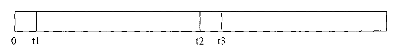
[0054] Such as image 3As shown, it is the time slot diagram of the normal light emission of the optical network unit. Assume that the light time slot length of a certain optical network unit is t1 when it is normally lighted. At this time, the ONU does not emit light until the central office will allocate a time slot for the ONU again after the time t2, and the ONU starts to emit light; that is, if the ONU is normal, then in (0, The optical network unit emits light in the time range of t1, the optical network unit does not emit light in the time range of (t1, t2), the optical network unit continues to emit light in (t2, t3), and so on;

[0055] Therefore, by detecting the optical power of the optical network unit twice at a set interval ...


PUM


Abstract

The invention relates to a passive optical network, in particular to a failure detection and control method of an optical network unit and an optical network unit, enhancing the failure detection capability of the optical network unit. The detection method of the optical network unit comprises the steps of: when outputting an optical detection SD signal of an optical module, reading the transmission optical power of the optical module twice, wherein the time interval of reading the optical power twice is set time; when reading the valves of the optical power twice, determining that the optical network unit fails, wherein the valuing range of the set time is larger than one luminous time slot of the optical network unit and smaller than the time interval of continuous normal two-time illumination of the optical network unit. Further, the optical network unit is controlled by cutting off a transmission power supply of the optical module. By adopting the method, the failure detection capability of the optical network unit is enhanced and the optical network unit with failure is prevented from influencing other normal ONU equipment by cutting off the transmission power supply of the optical module.

Description

technical field [0001] The invention relates to a passive optical network, in particular to a fault detection and control method of an optical network unit and an optical network unit. Background technique [0002] With the continuous enrichment of multimedia services, the demand for access network bandwidth is increasing. It is in this case that PON (passive optical network) is more and more widely used. access, which is not possible with traditional ADSL (Asymmetric Digital Subscriber Line). [0003] PON (Passive Optics Network, passive optical network) refers to the OLT (Optics Line Terminate, optical line terminal) as the central equipment and the ONU (Optics Network Unit, optical network unit) optical network unit as the terminal equipment and the ODN (Optics Distribution Network, a passive electronic equipment system composed of optical distribution network). Passive means that the optical distribution network between OLT and ONU does not have any active electronic e...

Claims


Application Information

Patent Timeline
Patent Type & Authority Applications(China)
IPC IPC(8): H04B10/08H04B10/079
CPCH04B10/07955H04B10/0793
Inventor 刘洋
Owner ZTE CORP
Why Eureka
Try Eureka