Supercharge Your Innovation With Domain-Expert AI Agents!

Yarn tuft transfer system

A technology for conveying systems and yarns, applied in flannelette looms, weaving, textiles and papermaking, etc., which can solve problems such as inability to provide positioning

Active Publication Date: 2010-05-19
BRINTONS CARPETAB
View PDF7 Cites 3 Cited by
  • Summary
  • Abstract
  • Description
  • Claims
  • Application Information

AI Technical Summary

Problems solved by technology

Existing systems do not provide sufficiently accurate and repeatable positioning

Method used


Image

  • Yarn tuft transfer system
  • Yarn tuft transfer system
  • Yarn tuft transfer system

Examples


Embodiment Construction

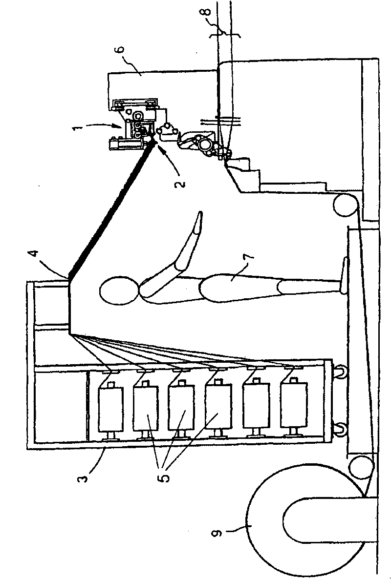
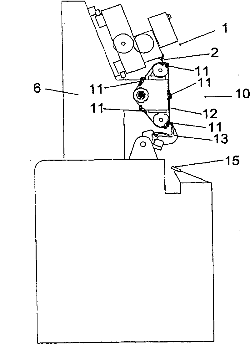
[0046] figure 1 with 2 A carpet loom in a preferred embodiment of the invention is shown in . The loom comprises one or more tuft forming units 1, each of which supplies yarn tufts to one or more different weaving points, and each unit comprises a yarn insertion device 2 for holding the yarn A movable creel 3 of the thread supply and a guide 4 for guiding the yarn from the supply 5 on the creel 3 to one or each tuft forming unit 1 . The creel 3 is located at the front of the loom and behind the weaver's station 7 . This is on the side of the loom opposite the warp beam (not shown) from which the warp yarns 8 are supplied. Alternatively, the creel 3 may be located above the rest of the loom 6 . The finished carpet is collected on roller 9.

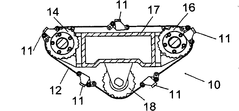
[0047] The loom comprises a yarn tuft delivery system 10 comprising five yarn tuft holders 11 mounted on a belt 12 . The belt 12 is arranged to move around a closed loop to sequentially feed each yarn tuft holder 11 to the yarn tuft i...


PUM


Abstract

A yarn tuft transfer system (10) for a carpet manufacturing machine, comprising one or more mounting devices (20) secured to a belt (12) or chain. The or each mounting device (20) includes a functional link element (21) having a mounting (24) for a payload, first securing means (27) rotatably mounted on the functional link element about a first axis for securing the functional link element onto the belt or chain at a first position, and second securing means (31) for securing the functional link element onto the belt or chain at a second position spaced from the first, said means being rotatable relative to the functional link element about a second axis. The first securing means is moveable relative to the second securing means along a line perpendicular to and intersecting the first and second axes. The system (10) further comprises a yarn tuft holder (11) mounted on the or each payload mounting (24). Also, a carpet manufacturing machine including the yarn tuft transfer system, and a method for making carpet using the carpet manufacturing machine.

Description

technical field [0001] The invention relates to devices for mounting payloads on belts or chains, in particular for conveyor systems. Background technique [0002] Attachments to drive belts (especially toothed drive belts) or chains are usually only at a single point, and generally the exact location of the attachment is not important for transport or conveying applications. The attachments can be made by protrusions which are pressed into or bonded to the back of the toothed belt or screwed or riveted through the toothed belt from the tooth side. In some instances, the attachment is concealed within the tooth, such as disclosed in EP1092657A, where a constrained insert is embedded in the tooth, or the attachment is concealed in the root between the teeth, as in JP2005- as disclosed in 075488A. In other cases, it protrudes from the tooth flank and requires changing the mating pulley to avoid the attachment, as disclosed in JP2000-095316A. A disadvantage of the single att...

Claims


Application Information

Patent Timeline
Patent Type & Authority Applications(China)
IPC IPC(8): D03D39/08
CPCD03D39/08
Inventor M·W·伯顿
Owner BRINTONS CARPETAB
Features
  • R&D
  • Intellectual Property
  • Life Sciences
  • Materials
  • Tech Scout
  • Unparalleled Data Quality
  • Higher Quality Content
  • 60% Fewer Hallucinations
Learn More