Device for hoisting prefabricated reinforced concrete column on site and walking technology thereof

A technology for reinforced concrete columns and prefabricated columns, which is applied in the directions of transportation and packaging, load suspending elements, and building materials processing, can solve the problems of increasing the use cost of hoisting equipment, high work intensity, and increasing hoisting weight, etc., and achieves economical efficiency. The benefits and comprehensive benefits are remarkable, the vertical process of righting is stable, and the construction productivity is improved.

Inactive Publication Date: 2010-05-26
DALIAN ZHUCHENG CONSTR GRP
View PDF0 Cites 20 Cited by
  • Summary
  • Abstract
  • Description
  • Claims
  • Application Information

AI Technical Summary

Problems solved by technology

[0002] At present, in my country's industrial plants, especially in heavy industrial plants, a large number of prefabricated reinforced concrete columns are used. According to the regulations of the existing building construction manual, the existing technical solution is to set pallets and rollers at the foot of the columns, and lay taxiways. At that time, the practices of various construction units were not uniform. Generally speaking, the pallets were made of steel plates, and the rollers were made of logs or steel pipes. It is very irregular, and a set of repeated facilities needs to be made for each cup foundation. The working method is very primitive, which not only wastes manpower and materials, but also has high work intensity and low efficiency. The sliding speed of the prefabricated columns is slow, which greatly increases the lifting equipment. Occupancy time, increase the cost of using a lot of hoisting equipment
[0003] At the same time, in the lifting stage of the installation process of these prefabricated columns, according

Method used


Image

  • Device for hoisting prefabricated reinforced concrete column on site and walking technology thereof
  • Device for hoisting prefabricated reinforced concrete column on site and walking technology thereof
  • Device for hoisting prefabricated reinforced concrete column on site and walking technology thereof

Examples


Embodiment Construction

[0022] The present invention will be further described below in conjunction with the accompanying drawings.

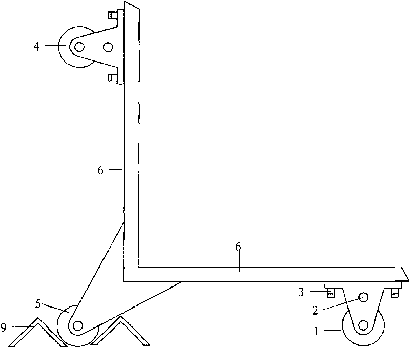
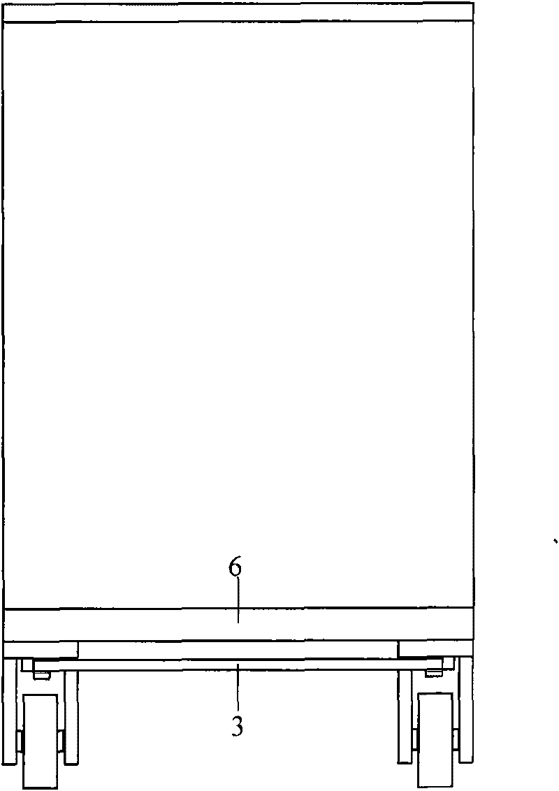
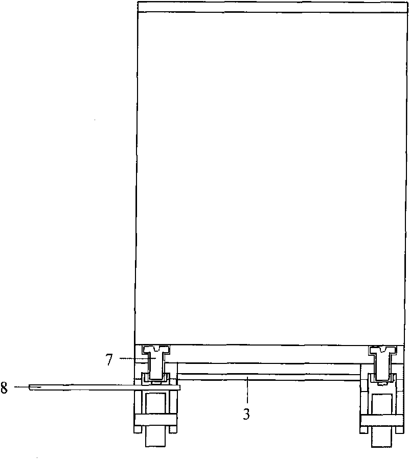
[0023] Depend on Figure 1-4 It can be seen that the steel track slab 10 is firstly laid from the foot position of the prefabricated column 12 to the vicinity of the cup foundation 14 . Insert the horizontal end of the supporting plate 6 of the present invention 11 under the column foot of the prefabricated column 12, and make the column foot support the vertical end of the carriage 6.

[0024] Bind one end of the wire rope to the other end of the prefabricated column 12 according to the design position, hang the other end of the wire rope on the hook of the crane 13, and then drag the prefabricated column 12 to translate along the predetermined line. When it is necessary to adjust the running direction, insert the steering lever 8 into the jack 2 on the wall of the steering wheel bracket, pull the steering lever 8, and make the rear steering wheel 1 rotate with the c...


PUM

PropertyMeasurementUnit
Thicknessaaaaaaaaaa

Abstract

The invention relates to the field of building operations, in particular to a device for hoisting prefabricated reinforced concrete column on site and a walking technology thereof. The purpose of the invention lies in providing a simple yet effect walking technology for hoisting prefabricated reinforced concrete column on site and the device for realizing the technology; the design is simple and the operation is effective. To achieve the purpose, the invention provides the following technical proposal: the device of the invention is composed of a wheeled supporting plate, steel sheets and braking angle iron and has the following characteristics: the supporting plate is a right-angle structure, the top of the right angle is provided with deflectable rolling-over wheels, the two ends of the supporting plate far away from the top of the right angle are respectively provided with deflectable wheels, rotary connecting rods are arranged on a deflectable wheel seat. With the device of the invention adopted, mechanical efficiency can be effectively improved, construction productivity can also be enhanced, thus accelerating construction progress and enjoying extremely noticeable economic benefits and comprehensive benefits.

Description

Technical field: [0001] The invention relates to the field of building construction, in particular to a device for hoisting a prefabricated reinforced concrete column on site and a walking technology. technical background: [0002] At present, in my country's industrial plants, especially in heavy industrial plants, a large number of prefabricated reinforced concrete columns are used. According to the regulations of the existing building construction manual, the existing technical solution is to set pallets and rollers at the foot of the columns, and lay taxiways. At that time, the practices of various construction units were not uniform. Generally speaking, the pallets were made of steel plates, and the rollers were made of logs or steel pipes. It is very irregular, and a set of repeated facilities needs to be made for each cup foundation. The working method is very primitive, which not only wastes manpower and materials, but also has high work intensity and low efficiency. T...

Claims


Application Information

Patent Timeline
IPC IPC(8): E04G21/14E04G21/16B66C13/08
Inventor 魏勇
Owner DALIAN ZHUCHENG CONSTR GRP
Why Eureka
Try Eureka