
Sighting telescope relay system capable of realizing high optical zoom by two-group movement

A sight and moving lens technology, which is applied in the direction of sighting devices, weapon accessories, offensive equipment, etc., can solve problems such as difficulties and limited potential

Inactive Publication Date: 2010-05-26
封雷
View PDF5 Cites 4 Cited by
  • Summary
  • Abstract
  • Description
  • Claims
  • Application Information

AI Technical Summary

Problems solved by technology

While achieving a high zoom ratio, it also has extremely high optical performance and a large field of view. However, due to the traditional way of moving and zooming with double positive lens groups, this optical type achieves a higher zoom ratio. has very limited potential, and it is very difficult to reach 7×

Method used


Image

  • Sighting telescope relay system capable of realizing high optical zoom by two-group movement
  • Sighting telescope relay system capable of realizing high optical zoom by two-group movement

Examples


Embodiment 1

[0023] This embodiment is a case where the present invention is applied to a scope for a 2-16×44 gun.

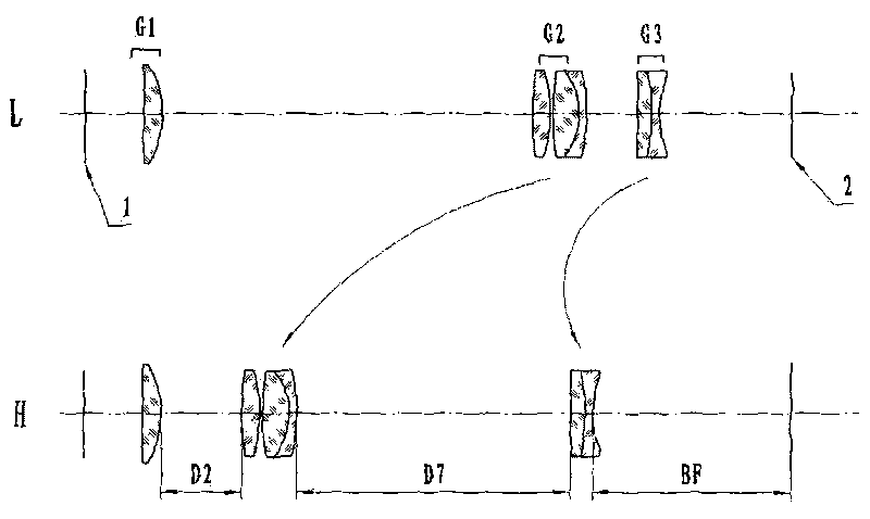
[0024] Figure 1 It is a schematic diagram of the lens distribution of the variable magnification transfer system according to Embodiment 1 of the present invention. Two lines with arrows represent respective movement trajectories of movement groups G2 and G3.

[0025] In the zoom relay system according to Embodiment 1 of the present invention, the first lens group G1 is composed of a single positive lens, which is slightly curved on the object side.

[0026] The second lens group G2 is composed of a single positive lens and a cemented positive lens from the object side.

[0027] The third lens group consists of a cemented negative lens.

[0028] Various data related to Example 1 are listed in Table 1.

[0029] In [Main Parameters], zoom ratio = maximum magnification of the zoom system / minimum magnification.

[0030] In [Variable Distance Data], B represents the magnifi...

Embodiment 2

[0045] The present embodiment is a case where the present invention is applied to a scope for a 3-30×56 gun.

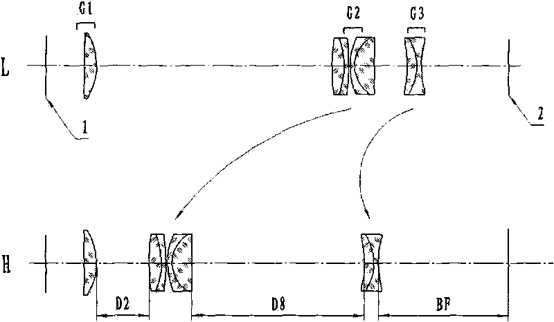
[0046] Figure II It is a schematic diagram of the lens distribution of the variable magnification transfer system according to Embodiment 2 of the present invention. Two lines with arrows represent respective movement trajectories of movement groups G2 and G3.

[0047] In the zoom relay system according to Embodiment 2 of the present invention, the first lens group G1 is composed of a single positive lens, which is slightly curved on the object side.

[0048] The second lens group G2 is composed of two cemented positive lenses from the object side.

[0049] The third lens group consists of a cemented negative lens with an object-side surface curved toward the object side and an image-side surface curved toward the image side.

[0050] Various data related to Example 2 are listed in Table 2.

[0051] Table 2


PUM


Abstract

The invention aims to provide a lens type zoom relay system of a sighting telescope for a gun, which has 6*-10* or higher optical zoom and has compactness and high optical performance. According to the inherent characteristics of the optical system described by the invention, the invention can ensure that under the condition that the zoom relay system has higher optical zoom and better optical performance, the conjugate distance of the whole zoom relay system is not larger than the conjugate distance in the process of realizing the optical zoom smaller than 4* in the conventional two-positive group movement zoom mode, thereby being very favorable for reducing the weight and the volume of products and improving the portability.

Description

technical field [0001] The present invention relates to a zoom and image transfer system of a gun sight, in particular to a lens type lens in a gun sight with a zoom ratio of 6×-10× or higher, compactness and high optical performance. Zoom system. Background technique [0002] The currently used gun sights use the traditional classic method of double positive group movement to achieve zooming as described in the optical design textbook. The only difference is that the number of lenses used in each lens group is different. , the two positive lens groups are the same in type, in which the first lens group on the object side moves to compensate for image plane drift, and the second lens group on the image side moves to achieve variable magnification. This zoom transfer system It can provide a sufficiently long exit pupil distance for the entire gun scope optical system, avoid damage to the human eye caused by recoil when shooting, and achieve better optical performance. Howev...

Claims


Application Information

Patent Timeline
Patent Type & Authority Applications(China)
IPC IPC(8): F41G1/387
Inventor 封雷
Owner 封雷
Learn More