Auto trimming oscillator

A technology of oscillator and oscillator frequency, which is applied in the automatic control of power, electrical components, etc., can solve problems such as difficult to find solutions, and achieve the effect of low-cost production

Inactive Publication Date: 2010-05-26
ATMEL CORP
View PDF6 Cites 8 Cited by
  • Summary
  • Abstract
  • Description
  • Claims
  • Application Information

AI Technical Summary

Problems solved by technology

Even with other RC oscillator topologies (e.g. with controlled currents to charge and discharge internal capacitors, etc.), it is not easy to find a solution where the frequency does not directly depend on the RC product

Method used


Image

  • Auto trimming oscillator
  • Auto trimming oscillator
  • Auto trimming oscillator

Examples


Embodiment Construction

[0013] Example automatic fine tuning oscillator

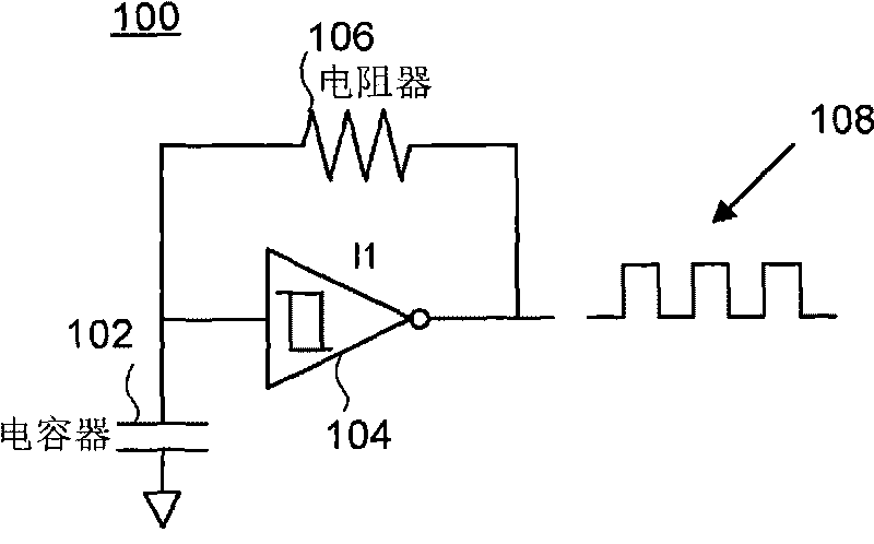
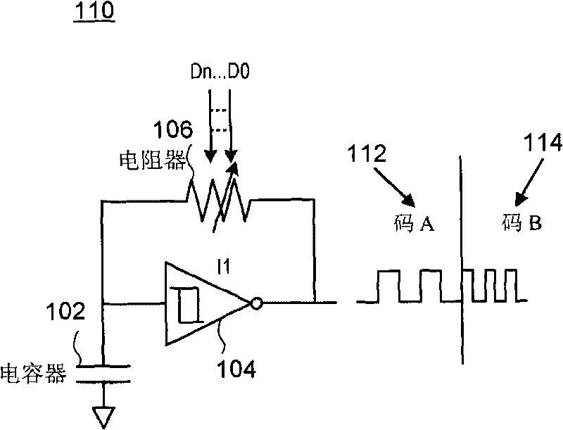
[0014] image 3 It is a block diagram of an exemplary automatic fine-tuning oscillator using SAR. In some implementations, the automatic fine-tuning oscillator 300 may include an oscillator 302, a frequency detector 304, a comparator 306, and a SAR 308. In the exemplary configuration shown, the SAR 308 outputs a digital code that can be used to iteratively fine-tune the oscillator 302 based on the difference between the oscillator 302 frequency (Fosc) and the reference clock frequency (Fref). In some implementations, the oscillator 302 may be a conventional RC oscillator, such as the RC oscillator 110 shown in FIG. 1B. Other types of oscillators (for example, Wien Bridge oscillator, Twin-T oscillator, phase shift oscillator) can also be used.

[0015] In some embodiments, the frequency detector 304 is figure 2 The number of edges of both the oscillator 302 clock and the reference clock are counted in the time period T defined by t...


PUM


Abstract

An auto trimming oscillator includes a Successive Approximation Register (SAR), a frequency detector and an n-bit comparator. The SAR is used to iteratively trim the oscillator output clock frequency based on a difference between a reference clock frequency and the oscillator output clock frequency. The oscillator is trimmed to deliver a clock frequency which is a closest match to the reference clock frequency.

Description

Technical field [0001] This subject matter generally relates to electronic circuits, and more specifically to fine-tuning oscillator circuits. Background technique [0002] Many modern electronic circuits (e.g., microcontrollers) use internal CMOS oscillators to generate clocks. In many applications, low-variation CMOS oscillators are required. Conventional CMOS oscillators are manually fine-tuned by test engineers using dedicated external tester resources. Some CMOS oscillators use a resistance-capacitance (RC) structure. [0003] Figure 1A shows a conventional RC oscillator with Schmitt trigger. The RC oscillator 100 includes a capacitor 102 (C), a Schmitt trigger 104 (11), and a resistor 106 (R). The output clock 108 has a frequency directly proportional to the RC product. A typical integrated polysilicon resistor can provide a relative frequency change of about + / -25%, and a typical integrated CMOS capacitor can provide a relative frequency change of about + / -15%. In this...

Claims


Application Information

Patent Timeline
Patent Type & Authority Applications(China)
IPC IPC(8): H03L7/00
CPCH03L7/085H03L7/089H03L7/0991
Inventor 塞巴斯蒂安·菲耶韦米歇尔·昆卡
Owner ATMEL CORP
Why Eureka
Try Eureka