Coupling underactuated integrated bionic hand device

A bionic hand and underactuated technology, applied in the field of anthropomorphic robot hands, can solve the problems of inability to achieve natural bending of joints, inability to achieve end pinching, and failure to integrate together, etc., and achieves a wide range of grasping objects, a simple structure, Motion stabilization effect

Inactive Publication Date: 2010-06-02
WUXI RES INST OF APPLIED TECH TSINGHUA UNIV +1
View PDF4 Cites 14 Cited by
  • Summary
  • Abstract
  • Description
  • Claims
  • Application Information

AI Technical Summary

Problems solved by technology

[0005] However, this type of underactuated adaptive bionic hand device has certain deficiencies: its fingers always rotate in a straight state before touching an object, which is not only quite different from human hand movements, but lacks anthropomorphism, and when the first finger segment After touching the object, before the second finger segment rotates to contact the object, the object may be pushed away by the first finger segment and leave the grasping range of the fingers; this type of bionic hand can only be grasped by holding When the end of the finger touches the object, the natural bending of each joint cannot be realized, so it is difficult to pull the object into the hand and grasp it firmly; it cannot perform the action similar to the empty hand "clenching fist" of a human hand, etc.
However, the coupled grasping and underactuated adaptive grasping of this device are separated. Only the upper part of the finger is used to realize the coupled grasping, and the lower part of the finger is used to realize the underactuated adaptive grasping. Simple synthesis, and does not really integrate the two grabbing methods

Method used


Image

  • Coupling underactuated integrated bionic hand device
  • Coupling underactuated integrated bionic hand device
  • Coupling underactuated integrated bionic hand device

Examples


Embodiment Construction

[0090] The specific structure and working principle of the present invention will be further described in detail below with reference to the accompanying drawings and embodiments.

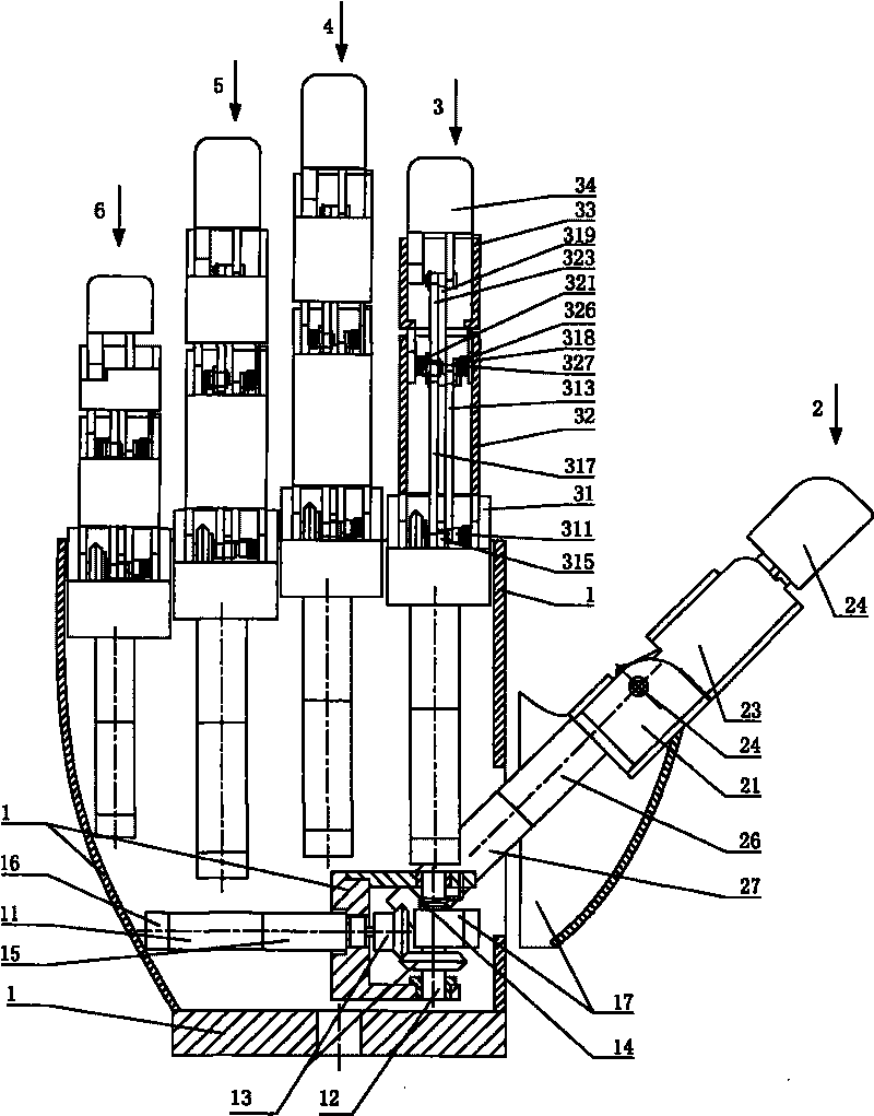
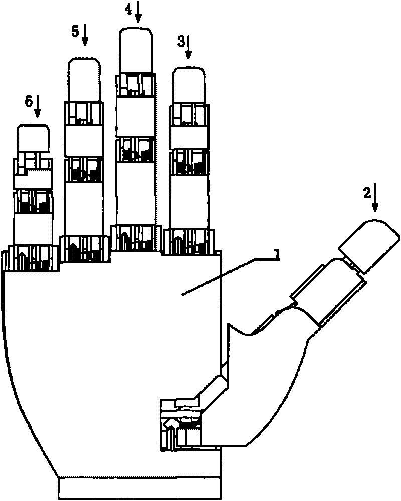
[0091] An embodiment of the coupled and underactuated integrated bionic hand device designed in the present invention, such as figure 1 , figure 2 , image 3 , Figure 4 , Figure 5 , Figure 45 , Figure 46 , Figure 47 , Figure 48 , Figure 49 , Figure 50 and Figure 51 As shown, the bionic hand device includes a thumb 2, an index finger 3, a middle finger 4, a ring finger 5, a little finger 6 and a palm.

[0092] The palm includes a palm skeleton 1, a palm motor 11, a palm joint shaft 12, a palm speed reducer 15, and a palm connecting plate 17; the palm motor 11 and the palm speed reducer 15 are fixedly connected to the palm skeleton 1, and the palm The output shaft of the motor 11 is connected with the input shaft of the palm speed reducer 15, the output shaft of the palm speed re...


PUM


Abstract

The invention relates to a coupling underactuated integrated bionic hand device, belonging to the technology field of humanoid robots; the bionic hand device comprises a thumb, a forefinger, a middle finger, a third finger, a little finger and a palm. The device comprises five individually controlled fingers and fifteen joint freedom degrees and is driven by six motors, and the device realizes the functions of highly simulating the appearance of a human hand and grabbing action and is suitable for the humanoid robot. The forefinger, the middle finger, the third finger, and the little finger adopt modular structures, and the commonality of parts is strong. All fingers utilize a connecting rod and a spring piece to form a coupling driving mechanism and an underactuated driving mechanism which are integrated, thereby comprehensively realizing special effect of integrating the coupling and underactuated self-adaption grabbing process. In the grabbing process, the device is turned by a coupling mode before an object is touched, the object is grabbed in a turning way by adopting an underactuated self-adaption mode after the object is touched, and the device can be automatically adaptive to the size and shape of the object. The output power of the bionic hand device is strong, the grabbing action is stable, the range of the grabbed objects is wide, the requirement to a control system is low, the structure is simple and the coupling underactuated integrated bionic hand device is suitable for long-time usage.

Description

technical field [0001] The invention belongs to the technical field of anthropomorphic robot hands, and in particular relates to a structural design of a coupled underactuated integrated bionic hand device. Background technique [0002] As an important part of the robot, the bionic hand device has become the focus and focus of research in the field of robotics in recent years. But in the current research, there are some technical difficulties. For example, in order to realize the multi-degree-of-freedom dexterous hand, more motors are needed. However, the increase in the number of motors will not only lead to a complex control system, but also make the entire device mechanism huge, destroying its anthropomorphism. Under-actuation technology is one of the solutions that can better solve this contradiction. By utilizing an underactuated mechanism, more joint degrees of freedom can be driven by fewer motors, thereby reducing the requirements on the control system. In partic...

Claims


Application Information

Patent Timeline
Patent Type & Authority Applications(China)
IPC IPC(8): B25J15/02B25J15/10B25J17/00
CPCB25J15/0009
Inventor 张文增赵得洋陈强都东孙振国
Owner WUXI RES INST OF APPLIED TECH TSINGHUA UNIV
Why Eureka
Try Eureka