Hydraulic stop iron mechanism of cutting device

A cutting machine and hydraulic technology, applied in metal processing and other directions, can solve the problems of time-consuming and labor-intensive enterprises, large production volume, and even finding the correct position after trial cutting, and achieve the effect of improving work efficiency.

Inactive Publication Date: 2010-06-02
YANCHENG ZHICHENG MASCH MFG CO LTD
View PDF0 Cites 3 Cited by
  • Summary
  • Abstract
  • Description
  • Claims
  • Application Information

AI Technical Summary

Problems solved by technology

[0002] The cutting machine generally realizes the precise half-cutting of the material through the pressure sensor and the iron stop mechanism. At present, the iron stop mechanism adopts the manual adjustment method of the worm gear or the screw nut. Due to the processing accuracy and the elasticity of the processed material Due to deformation and other reasons, it is often necessary to repeatedly calibrate the knife, and sometimes even to find the correct position after trial cutting, which brings a lot of inconvenience to production. It is necessary to re-set the knife after changing the knife mold or the knife mold is worn. Now The product is updated quickly and the production volume is also large. The time-consuming and labor-intensive tool setting process is increasingly criticized by enterprises.

Method used


Image

  • Hydraulic stop iron mechanism of cutting device
  • Hydraulic stop iron mechanism of cutting device
  • Hydraulic stop iron mechanism of cutting device

Examples


Embodiment Construction

[0013] The present invention will be further described below in conjunction with the accompanying drawings and embodiments.

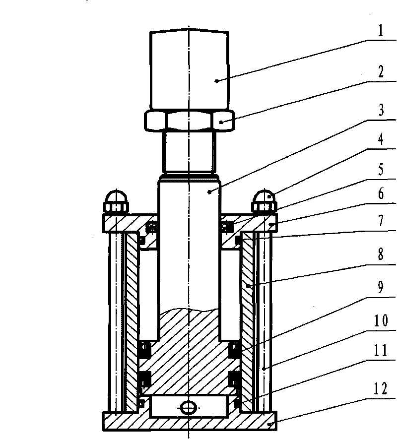
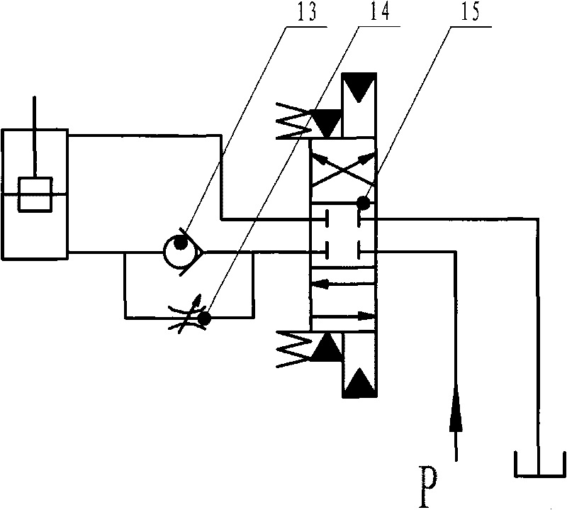
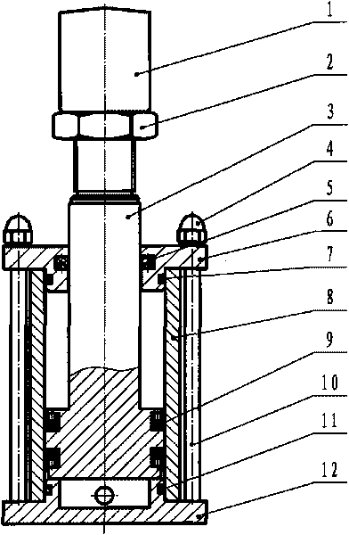
[0014] exist figure 1 Among them, the upper end cover 6, the cylinder barrel 8, and the lower end cover 12 are connected by a tie rod 10, the lower end of the tie rod 10 is threadedly connected with the lower end cover, the upper end of the tie rod 10 is fixed by the cap nut 4 and the upper end cover 6, and the cylinder barrel 8 and the upper end cover 6, the lower end O-rings 7 and 11 are respectively arranged between the covers 12 to play a sealing role. The piston rod 3 passes through the upper end cover 6 and is slidably fitted. The Y-shaped sealing ring 5 is in the groove of the upper end cover 6 to play a sealing role. The cylinder There is a sliding fit between the cylinder 8 and the piston rod 3, and two Y-shaped sealing rings 9 for the piston are installed in the groove of the piston rod 3, which act as a two-way seal. tight. figure 2 It is ...


PUM


Abstract

The invention relates to a hydraulic stop iron mechanism of a cutting device, which comprises a stop iron, an upper end cover, locking nuts, a piston rod, a lower end cover, a pull rod, a fixing nut, a cylinder barrel and sealing members, and also comprises a change valve, a check valve, an adjustable restrictor valve and the like. The upper end cover, the cylinder barrel and the lower end cover are connected by the pull rod and are fixed by the locking nuts, the piston rod passes through the upper end cover and is arranged in the cylinder barrel; the stop iron and the piston rod are screwed and locked by the locking nuts; the piston rod, the upper end cover and the cylinder barrel are in sliding fit and the piston rod is provided with the sealing members; the cylinder barrel, the upper end cover and the lower end cover are in transition fit and the cylinder barrel is provided with the sealing member; the upper end cover is provided with an oil hole communicated with an oil outlet of the change valve, the check valve is connected in parallel with the adjustable restrictor valve, an oil outlet of the check valve is communicated with an oil hole on the lower end cover, and an oil inlet is communicated with the other oil outlet of the change valve. The invention can be automatically and accurately positioned through a hydraulic system without manual adjustment, saves time and labor, and improves the working efficiency.

Description

technical field [0001] The invention relates to a cutting machine for processing sheet-shaped flexible materials in the light industry, especially a cutting machine with a half-cut function. Background technique [0002] The cutting machine generally realizes the precise half-cutting of the material through the pressure sensor and the iron stop mechanism. At present, the iron stop mechanism adopts the manual adjustment method of the worm gear or the screw nut. Due to the processing accuracy and the elasticity of the processed material Due to deformation and other reasons, it is often necessary to repeatedly calibrate the knife, and sometimes even to find the correct position after trial cutting, which brings a lot of inconvenience to production. It is necessary to re-set the knife after changing the knife mold or the knife mold is worn. Now The product update is very fast, and the production volume is also very large. The time-consuming and labor-intensive tool setting proce...

Claims


Application Information

Patent Timeline
Patent Type & Authority Applications(China)
IPC IPC(8): B26D7/26
Inventor 朱春才
Owner YANCHENG ZHICHENG MASCH MFG CO LTD
Why Eureka
Try Eureka