Semi water gas generating system

A generation system, semi-water gas technology, applied in the manufacture of combustible gas, petroleum industry, etc., can solve the problems of reducing the quality of semi-water gas, increasing compressor power consumption, reducing system production efficiency, etc., to reduce blowing time and increase gas production time , the effect of simple pipeline configuration

Inactive Publication Date: 2010-06-02
HUBEI SANNING CHEM
View PDF7 Cites 0 Cited by
  • Summary
  • Abstract
  • Description
  • Claims
  • Application Information

AI Technical Summary

Problems solved by technology

The disadvantage is that when the gas furnace is turned from blowing to upward blowing, a large amount of blowing gas accumulated in the gas furnace's upstream pipe and dust collector enters the gas system, reducing the quality of semi-water gas per unit time; for synthetic ammonia alcohol production devices (especially those with relatively high ammonia alcohol ratio) device) is unfavorable, increasing compressor power consumption and reducing system production efficiency

Method used


Image

  • Semi water gas generating system
  • Semi water gas generating system
  • Semi water gas generating system

Examples


Embodiment Construction

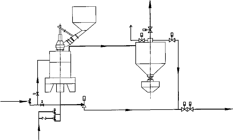
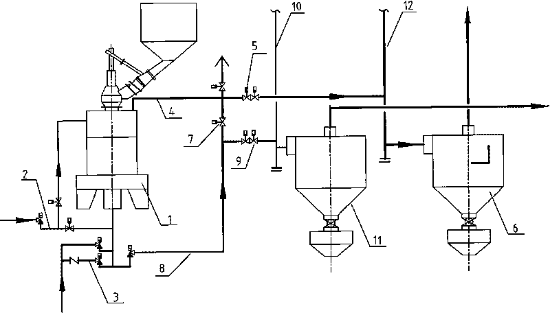
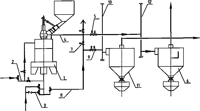
[0013] Such as figure 1 As shown, the present invention comprises a gas furnace 1, a steam pipe 2 and an air inlet pipe 3 are connected to the gas furnace 1, and a plurality of gas furnaces 1 form a single system, and the upstream pipe 4 of the gas furnace 1 passes through the air return valve 5 and the air return valve 5 all the way. Blowing gas main pipe 12 is connected, and blowing gas main pipe 12 is connected with blowing main pipe dust collector 6. The other way of the upward gas pipe 4 of the gas furnace 1 is merged with the upward gas valve 7 and the downward gas pipe 8, and then enters the single-system gas main pipe through the coal main valve 9. 10. The single-system gas main pipe 10 communicates with the gas main pipe dust collector 11. Four gas furnaces 1 form a single system. The upward gas valve 7 and the blowing return valve 5 are delay valves.

[0014] The working principle of the present invention is as follows: steam passes through the steam pipe 2, and ai...


PUM


Abstract

The invention relates to a semi water gas generating system comprising a gas stove connected with a steam pipe and an air inlet pipe. A single system is formed by a plurality of gas stoves; one ascending pipe of the gas stove is communicated with a blowing main pipe by a blowing return-air valve; the blowing main pipe is communicated with a blowing main pipe dust collector; the other ascending pipe of the gas stove is merged with a descending gas pipeline by an ascending gas valve and then enters a single system gas main pipe by a gas main valve; and the single system gas main pipe is communicated a gas main pipe dust collector. The invention reduces the shared passages of ascending gas and blowing gas in a process so as to prevent a great amount of blowing gas remained in the shared passages from entering the gas system in the transfer process from gas stove blowing to gas preparation; and unavoidable blowing gas in the shared passages in the flow can be used as adjustable gas which can be sent to the blowing gas system or the gas system by a delay or underlay measure as required. The invention increases effective gas components in the gas and increases the adjustment range of circulating hydrogen in the production system.

Description

technical field [0001] The invention relates to a semi-water gas generation system in the field of atmospheric pressure fixed bed intermittent coal gasification technology in the coal chemical industry. Background technique [0002] In the field of atmospheric fixed bed intermittent coal gasification, the "one furnace, one device" device is generally used, that is, one gas furnace is equipped with one dust collector to remove dust from blown gas and semi-water gas. The process is that the blowing gas from the gas furnace blowing or the upward gas from the gas production enters the dust collector through the upward pipe, and then passes through the recovery valve of the blowing gas or the upstream gas valve and the main coal valve respectively. The disadvantage is that when the gas furnace is turned from blowing to upward blowing, a large amount of blowing gas accumulated in the gas furnace's upstream pipe and dust collector enters the gas system, reducing the quality of semi...

Claims


Application Information

Patent Timeline
Patent Type & Authority Applications(China)
IPC IPC(8): C10J3/20C10J3/84
Inventor 殷银华李先云
Owner HUBEI SANNING CHEM
Why Eureka
Try Eureka