Supercharge Your Innovation With Domain-Expert AI Agents!

Reduced pressure type ball valve

A ball valve and pressure reducing seat technology, applied in the field of ball valves and pressure reducing ball valves, can solve the problems of inability to automatically achieve pressure reduction, low working stability, and unsuitable general use, and achieve good pressure reduction and anti-reverse effects and stable work. High performance and wide application range

Inactive Publication Date: 2011-11-16
安徽凯美尔厨卫有限公司
View PDF1 Cites 0 Cited by
  • Summary
  • Abstract
  • Description
  • Claims
  • Application Information

AI Technical Summary

Problems solved by technology

But this kind of decompression valve group mainly has the following disadvantages: 1. Its structure is complicated, so it is not suitable for general use; 2. It cannot automatically achieve the decompression effect, and manual operation is required during use, which increases the cumbersome operation; 3. Stable work Low reliability, high manufacturing cost

Method used


Image

  • Reduced pressure type ball valve
  • Reduced pressure type ball valve
  • Reduced pressure type ball valve

Examples


Embodiment Construction

[0029] The following are specific embodiments of the present invention and in conjunction with the accompanying drawings, the technical solutions of the present invention are further described, but the present invention is not limited to these embodiments.

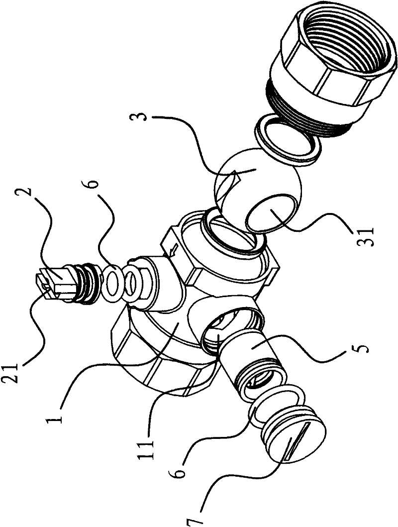
[0030] like figure 1 As shown, the decompression ball valve includes a valve body 1 and a bonnet that is threadedly connected with the valve body 1, and a valve core 3 with a through hole 31 is provided in the valve body 1, and the valve body 1 and the bonnet are respectively A valve seat is provided, and the two valve seats abut against the valve core 3 to limit the position of the valve core 3 . A valve stem 2 is provided inside the valve body 1 , one end of the valve stem 2 extends out of the valve body 1 , and the other end of the valve stem 2 is connected with the valve core 3 . Two annular grooves are arranged on the valve stem 2, and O-shaped sealing rings 6 are respectively arranged in the annular grooves, so that...


PUM


Abstract

The invention provides a reduced pressure type ball valve, belonging to the technical field of the valve. The ball valve solves the problem that the existing ball valve has poor pressure reduction effect and the pressure reduction structure is very complicated. The reduced pressure type ball valve comprises a valve body, a valve rod and a spherical spool, wherein the spool is arranged in the valve body, the spool is provided with a through-hole, the valve rod passes through the valve body, the inner end is connected with the spool, the outer end extends outside the valve body, a pressure reduction part is fixedly connected with the inside of the through-hole of the spool, and a permeable gap is arranged between the pressure reduction part and the inner wall of the through-hole. The reduced pressure type ball valve has the advantages of simple structure, automatic pressure reduction function and good pressure reduction effect.

Description

technical field [0001] The invention belongs to the technical field of valves, and relates to a ball valve, in particular to a pressure-reducing ball valve. Background technique [0002] The ball valve came out in the 1950s. With the rapid development of science and technology, the continuous improvement of production technology and product structure, it has rapidly developed into a major valve category in just 50 years. The ball valve is mainly used to cut off, distribute and change the flow direction of the medium in the pipeline. There is a channel inside the ball valve core, and the valve core rotates under the action of the valve stem. When it is turned to a certain position, the ball valve is fully open; To another position, the ball valve is closed. However, during the use of ordinary ball valves, due to the excessive water pressure or oil pressure passing through the valve body, the water flowing into the pipeline connected to the valve body is too fast, which is ea...

Claims


Application Information

Patent Timeline
Patent Type & Authority Patents(China)
IPC IPC(8): F16K5/06F16K5/08F16K27/06
Inventor 冯江波
Owner 安徽凯美尔厨卫有限公司
Features
  • R&D
  • Intellectual Property
  • Life Sciences
  • Materials
  • Tech Scout
  • Unparalleled Data Quality
  • Higher Quality Content
  • 60% Fewer Hallucinations
Learn More