
Boiler with double fire grates and double combustion chambers

A dual-combustion chamber and dual-grate technology, which is used in combustion equipment, solid fuel combustion, lighting and heating equipment, etc., can solve the problems of low furnace temperature and difficulty in air supply, and achieve the improvement of furnace temperature and utilization rate. The effect of expanding the range of adaptability

Inactive Publication Date: 2011-03-23
董振友
View PDF0 Cites 0 Cited by
  • Summary
  • Abstract
  • Description
  • Claims
  • Application Information

AI Technical Summary

Problems solved by technology

[0004] The object of the present invention is to provide a boiler with double grates and double combustion chambers, which fundamentally changes the structural design of the grates and combustion chambers, thereby fundamentally solving the difficulty of air supply in the middle of large and medium-sized boilers and the low temperature of the furnace. The air supply arrangement is more ideal, the furnace temperature is increased, and it is more suitable for burning coal with a lower calorific value.

Method used


Image

  • Boiler with double fire grates and double combustion chambers
  • Boiler with double fire grates and double combustion chambers
  • Boiler with double fire grates and double combustion chambers

Examples


Embodiment Construction

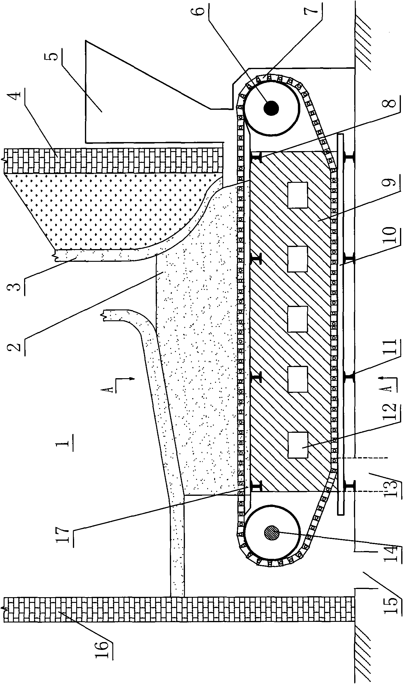
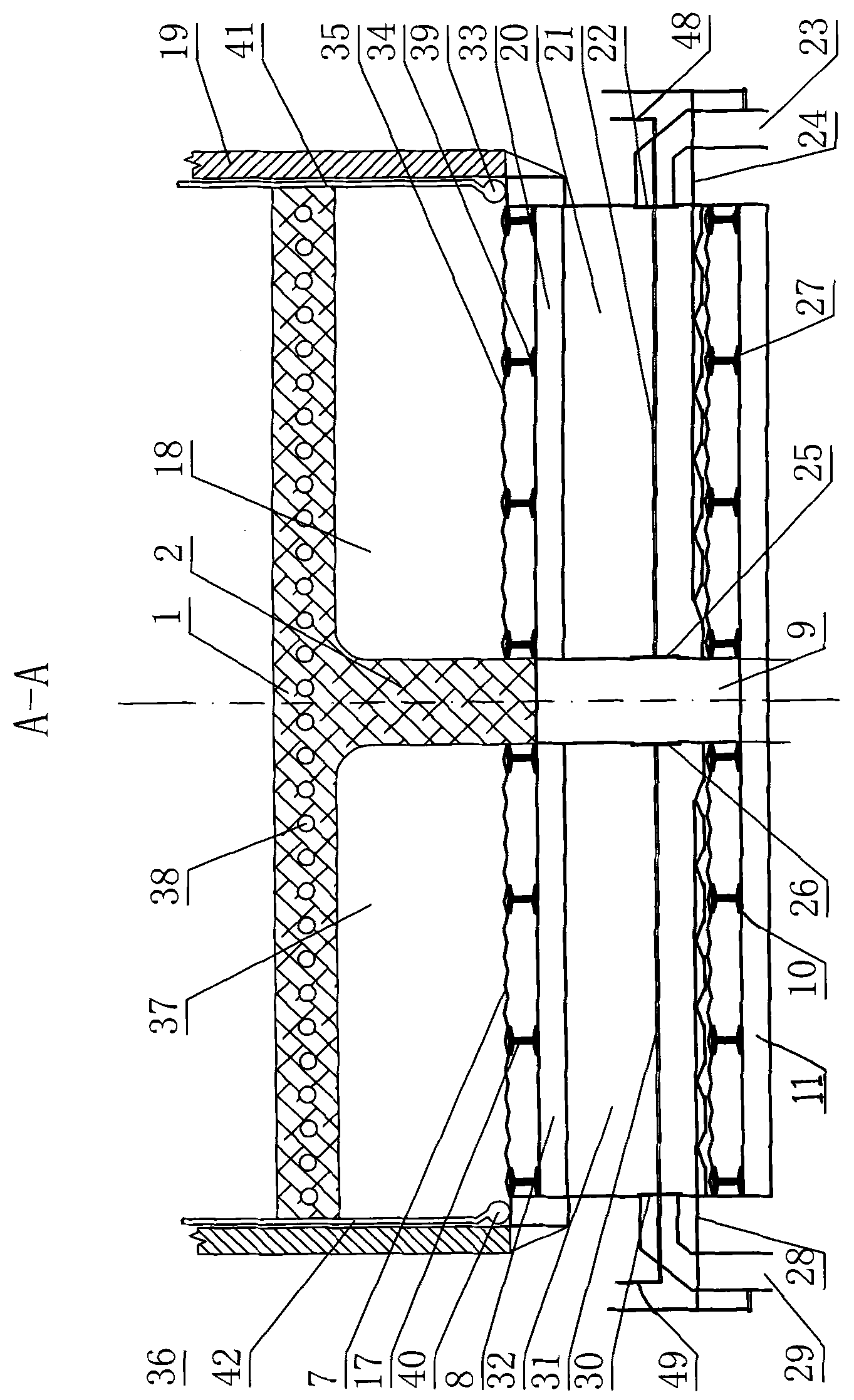
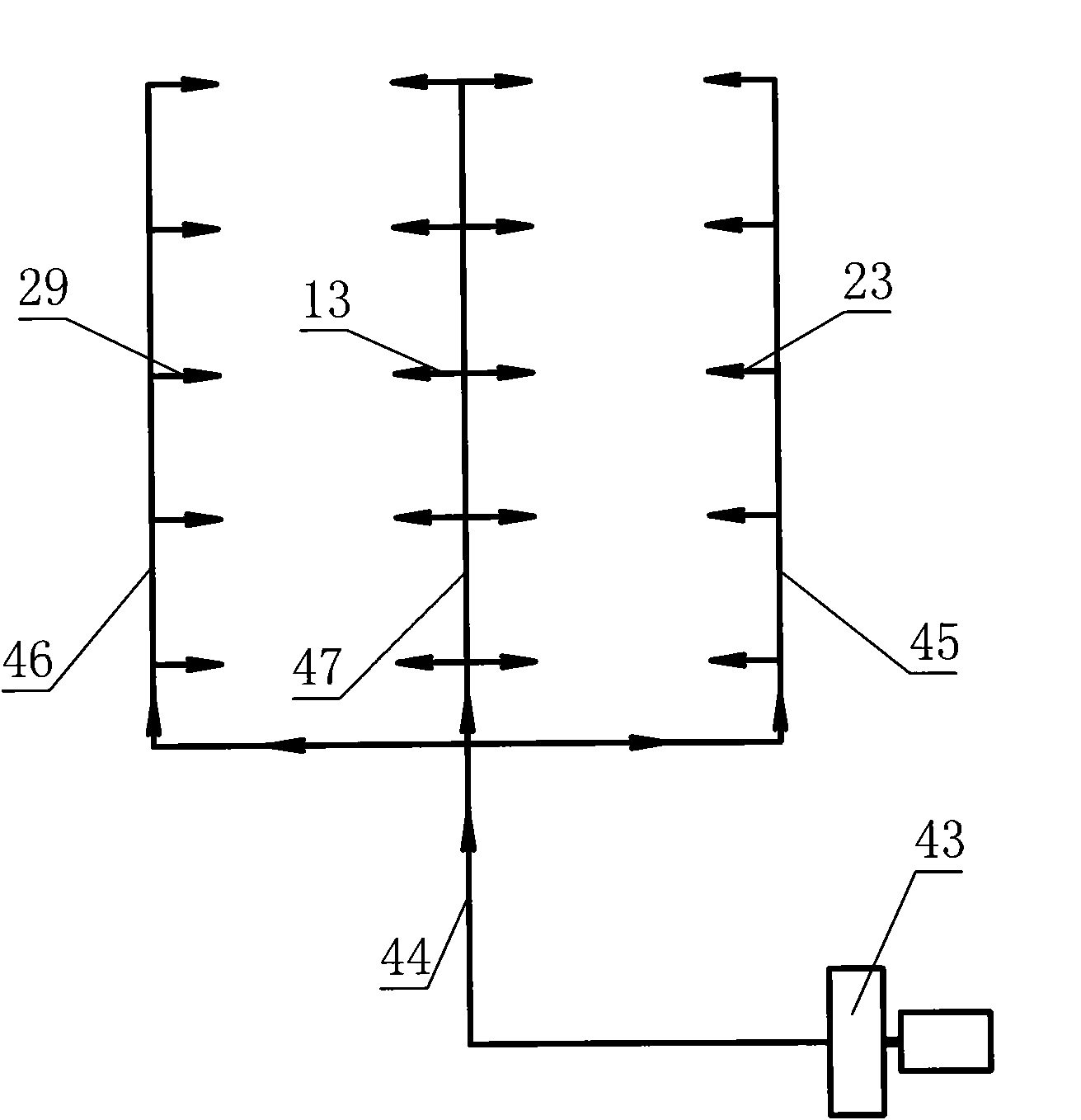
[0015] according to Figure 1~3 The specific structure of the present invention will be described in detail. The present invention reforms the existing coal-fired seam-fired boiler, still including the combustion chamber surrounded by the front furnace wall 4, the rear furnace wall 16, the left furnace wall 36, the right furnace wall 19, the front arch 3, and the rear arch 1, and the combustion chamber The double-layer fire grate driven by the front and rear shafts 6 and 14, the air chambers between the upper and lower layers of the fire grate, and the boiler blower 43 are set under the chamber to keep the boiler shape structure, the fire grate shape and the size of the front and rear shafts 6 , The original state of 14 remains unchanged.

[0016] The upper and lower layers of the fire grate are disconnected in the middle to form the left and right fire grate 7, 35, and the middle bellows 9 is set between the left and right fire grate 7, 35. The left and right sides of the l...


PUM


Abstract

The invention relates to a boiler with double fire grates and double combustion chambers, which basically solves the problems of difficult air supply in the lower furnace box temperature of large and medium sized boilers. The boiler comprises combustion chambers, fire grates, air chambers and a boiler blower, wherein the fire grates are arranged below the combustion chambers; the air chambers arearranged between upper layers and lower layers of the fire grates; the upper layers and the lower layers of the fire grates are all disconnected in the middle to form a left fire grate and a right fire grate; a middle air box is arranged between the left fire grate and the right fire grate and divides the air chambers into a left air chamber and a right air chamber; a left ventilation opening anda right ventilation opening are respectively arranged at the left side and the right side of the middle air box and respectively communicated with the left air chamber and the right air chamber; an air inlet is arranged at the lower part of the middle air box and communicated with a main air duct of the boiler blower through a branch air duct; and a fire division wall connected with a front arch and a back arch is constructed above the middle air box and divides the combustion chambers into a left combustion chamber and a right combustion chamber. The invention improves the utilization ratio of coal, reduces the power consumption of the boiler blower, and realizes the purpose of energy saving. The invention has wider adaptability to fuel and is especially suitable for reconstruction and use of the large and medium sized boilers.

Description

technical field [0001] The invention relates to an improved coal-fired bed-fired boiler, in particular to a double-grate double-chamber boiler with more reasonable structural design, high efficiency and energy saving. Its adaptability to fuel is wider, especially suitable for the transformation and use of large and medium-sized boilers. Background technique [0002] At present, coal-fired seam-fired boilers are designed to use AII bituminous coal, that is, bituminous coal with a calorific value of about 4,500 kcal / kg. When the coal calorific value is lower than 4,300 kcal / kg, the fire bed will be irregular in the combustion chamber. , the flame is not concentrated, the ignition point is scattered, and the carbon content of the slag also increases significantly. If the calorific value is around 4000 kcal / kg, there will be a fire failure, and it is difficult for the operator to control the combustion conditions of the boiler. [0003] The main reasons why large and medium-siz...

Claims


Application Information

Patent Timeline
Patent Type & Authority Patents(China)
IPC IPC(8): F23B10/02
Inventor 董振友
Owner 董振友
Learn More