Combined high-temperature and durable creeping clamp

A combination and fixture technology, applied in the direction of measuring devices, instruments, scientific instruments, etc., can solve the problems of increasing the cost of testing, and achieve the effects of reducing test costs, avoiding replacement, and low manufacturing costs

Active Publication Date: 2010-06-02
AVIC BEIJING INST OF AERONAUTICAL MATERIALS
View PDF1 Cites 12 Cited by
  • Summary
  • Abstract
  • Description
  • Claims
  • Application Information

AI Technical Summary

Problems solved by technology

In addition, the fixture replacement caused by the deformation of the fixture also increases the cost of testing

Method used


Image

  • Combined high-temperature and durable creeping clamp
  • Combined high-temperature and durable creeping clamp
  • Combined high-temperature and durable creeping clamp

Examples


Embodiment 1

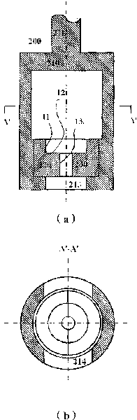
[0019] First, refer to figure 2 (a) and figure 2 (b). Such as figure 2 (a) and figure 2 As shown in (b), the combined permanent creep clamp 200 includes a clamp body 210 and a pair of force transmission members 220 and 230 . The clamp body 210 is used to connect with a durability or creep testing machine and carry the tensile load from the testing machine. The clamp main body includes a connecting rod 211 directly connected to the testing machine and a frame member integrated with the connecting rod 211, in which a cavity 212 for accommodating the force transmission members 220 and 230 is formed and is used for receiving and The through hole 213 at the end of the sample is taken out. The cavity 212 has a side opening 214 for receiving and taking out the force transmission members 220 and 230 , and the opening 214 has a size corresponding to or slightly larger than the outer contour size of the force transmission members 220 and 230 . At the bottom of the cavity 212, ...

Embodiment 2

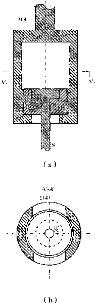
[0024] Below, refer to Figure 4 Another structure of the combined permanent creep clamp according to the present invention is described. The difference between this structure and the above structure is that the groove of the cavity of the clamp body 410 is designed to present a certain angle with the loading direction, and the range of the angle is 40° to 90°, preferably 45° to 80°, more preferably 50-70°. Corresponding to this angle, the bottom surfaces of the grooves of the force transmission members 420 and 430 can also be designed to present a certain angle with the loading direction, and the angle ranges from 40° to 90°, preferably from 45° to 80°, more preferably from 50° to 70°. The bottom surfaces of the grooves of the force transmission members 420 and 430 are preferably parallel to the bottom surfaces of the grooves of the cavity of the jig body 410 . In this example, if Figure 4 As shown, the end of the sample P' has a slope that matches the bottom of the groo...

example 1

[0028] The shoulder at the end of the sample is a cylinder with a diameter of 12 mm and a height of 6 mm, and the middle section is a cylinder with a diameter of 5 mm and a height of 32 mm. The surface 11 of the force transmission member is 6 mm high, and the surface 13 is 6 mm high. Two identical force transmission members are combined to form a cylinder with an outer diameter of 14mm and a height of 12mm. The inside of the cylinder includes a hollow portion with a diameter of 12 mm and a height of 6 mm and a hollow portion of 12 mm in diameter and a height of 6 mm in a concentric manner. The jig main body is a cylinder with an outer diameter of 25 mm, the height of the bottom of the cylinder is 6 mm, and the diameter of the through hole 213 is 5 mm. The clamp body and the force transmission member are manufactured from DZ125 alloy by known casting and machining methods.


PUM

PropertyMeasurementUnit
heightaaaaaaaaaa

Abstract

The invention belongs to a mechanics performance testing technology, relating to a combined high-temperature and durable creeping clamp. The clamp comprises a clamp body and two force transferring members, wherein the clamp body is a cavity, openings with the size corresponding to that of the force transferring members are arranged on the clamp body, and the bottom of the clamp body is provided with a through hole adapting to the end of a sample; the two force transferring members are arranged at the bottom of the clamp cavity, the inner surface of each force transferring member is divided into two parts, one part is a pressed part corresponding to the pressed part of the surface of the sample, and the other part is a part corresponding to the pulled part of the surface of the sample, and the two parts of the inner surfaces of the force transferring members are matched with the ends of the sample. The loaded face of the sample can load even loads according to the combined high-temperature and durable creeping clamp so that the problem of test data invalidity caused by uneven stressing in the testing process can be avoided.

Description

technical field [0001] The invention belongs to the mechanical performance testing technology, and relates to a combined high-temperature durable creep fixture. Background technique [0002] As we all know, durability and creep are used to describe the performance of high temperature structural materials to withstand constant load for a long time under high temperature conditions. In order to obtain the durability and creep strength of the material, the material must be processed into a durability and creep specimen and loaded into a durability and creep testing machine for a durability and creep test. Endurance and creep testing machines are generally equipped with clamps for securing the specimens to the testing machine. [0003] Between conventional permanent and creep specimens and fixtures, threaded connections are usually used to evenly transfer the applied load to the working section of the specimen through the threads. However, there is a problem of high temperatur...

Claims


Application Information

Patent Timeline
Patent Type & Authority Applications(China)
IPC IPC(8): G01N3/04
Inventor 李影于慧臣
Owner AVIC BEIJING INST OF AERONAUTICAL MATERIALS
Why Eureka
Try Eureka