Scrap remover of film sticking machine

A film laminating machine and electrode technology, which is applied in the manufacture of ships or lead-in wires, can solve problems such as falling on the substrate

Inactive Publication Date: 2010-06-02
SICHUAN COC DISPLAY DEVICES
View PDF0 Cites 4 Cited by
  • Summary
  • Abstract
  • Description
  • Claims
  • Application Information

AI Technical Summary

Problems solved by technology

[0004] The purpose of the present invention is to provide a chip removal device for a film laminating machine, which can solve the problem that in the prior art, due to the different material properties

Method used


Image

  • Scrap remover of film sticking machine
  • Scrap remover of film sticking machine
  • Scrap remover of film sticking machine

Examples


Embodiment Construction

[0013] The present invention will be described in detail below with reference to the accompanying drawings and in combination with embodiments.

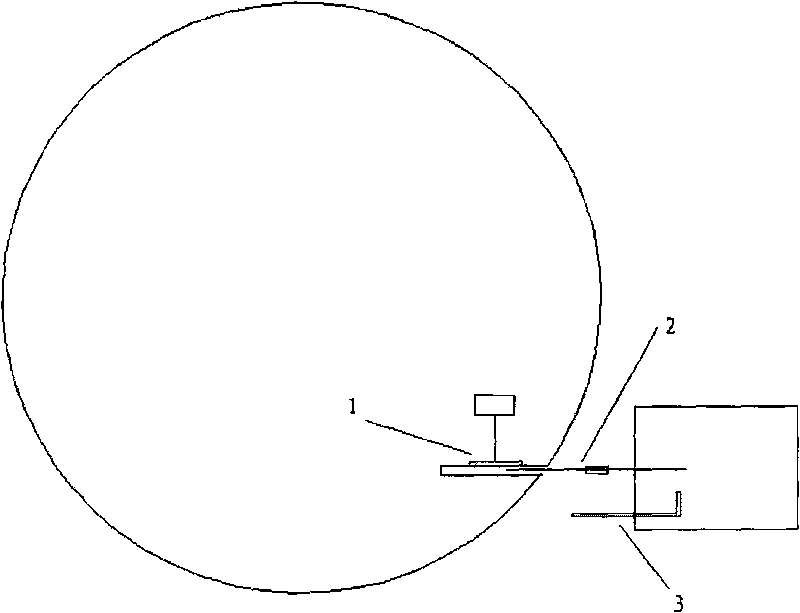
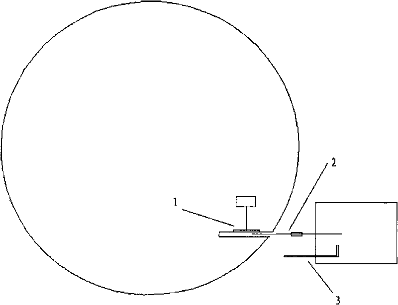
[0014] figure 1 It shows a schematic diagram of a chip removal device for a film laminating machine according to an embodiment of the present invention, including:

[0015] The first electrode 1 is located in the rotary vacuum suction barrel of the film laminating machine;

[0016] a second electrode 3, which is located on the guide rail of the cutting blade 2 of the film applicator, and whose polarity is opposite to that of the first electrode; and

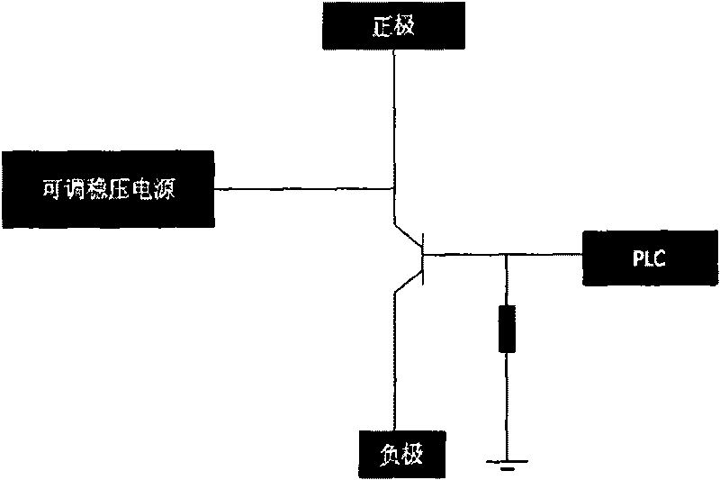
[0017] A power supply (not shown in the figure), which is used to supply power to the first electrode 1 and the second electrode 3 .

[0018] The above-mentioned embodiment forms positive and negative electrodes, and adopts the method of electrostatic attraction, so that the fine chips generated after cutting are adsorbed on the electrodes, so that they will not adhere to the substrat...


PUM


Abstract

The invention provides a scrap remover of a film sticking machine, which comprises a first electrode, a second electrode and a DC power source, wherein the first electrode is positioned in a rotating vacuum sucking drum of the film sticking machine; the second electrode is positioned on a guide rail of a cutting blade of the film sticking machine, and the polarity of the second electrode is opposite to the polarity of the first electrode; and the DC power source is used for supplying power for the first electrode and the second electrode. In the invention, the positive electrode and the negative electrode are formed, and an electrostatic attraction method is used, so that the scraps produced by cutting can be adsorbed on the electrodes and can not be attached to the substrate but pressed under the film in the process of film sticking, thereby solving the problems in the existing technology that the splattering scraps produced in the process of cutting the DFR film for shielding fall on the substrate and are pressed under the DFR film due to different material properties of the DFR film, and the scraps witness large defects after being exposed to light.

Description

technical field [0001] The invention relates to the field of plasma display screens, in particular to a chip removal device for a film laminating machine. Background technique [0002] At present, the production of PDP (Plasma Display Panel, plasma display screen) barrier mainly includes sticking photosensitive film, exposure, development, sandblasting and direct exposure of photosensitive barrier material wet etching. In the former method, the photosensitive film contains fiber material to increase the strength, so as to protect the undeveloped barrier material in the sandblasting of the subsequent process. This feature determines that the material will have somewhat anisotropic stress distribution during cutting, resulting in the detachment of fine chips. In the film lamination process of the existing film laminating machine, the substrate has not yet fully entered the laminating area when the film is cut, so if the fine particles of the barrier material fall, they will a...

Claims


Application Information

Patent Timeline
IPC IPC(8): H01J9/24
Inventor 姚纯
Owner SICHUAN COC DISPLAY DEVICES
Why Eureka
Try Eureka