Application of composite power cable connection box with optical fiber arranged in center of conductor

A power cable and connection box technology is applied to the application field of a composite power cable connection box with an optical fiber set in the center of the conductor. The effect of improving reliability and efficiency and reducing construction costs

Inactive Publication Date: 2010-06-02
SHENYANG FURUKAWA CABLE
View PDF5 Cites 15 Cited by
  • Summary
  • Abstract
  • Description
  • Claims
  • Application Information

AI Technical Summary

Problems solved by technology

[0005] The purpose of the present invention is to provide an application of a composite power cable connection box with an optical fiber in the center of the conductor, which solves the problems of laborious movement of the optical fiber, inaccurate temperature measurement at the joint, and easy damage to the optical fiber in the existing connection process. Reasonable technology, easy on-site construction, simple and fast operation, no

Method used


Image

  • Application of composite power cable connection box with optical fiber arranged in center of conductor
  • Application of composite power cable connection box with optical fiber arranged in center of conductor
  • Application of composite power cable connection box with optical fiber arranged in center of conductor

Examples


Embodiment Construction

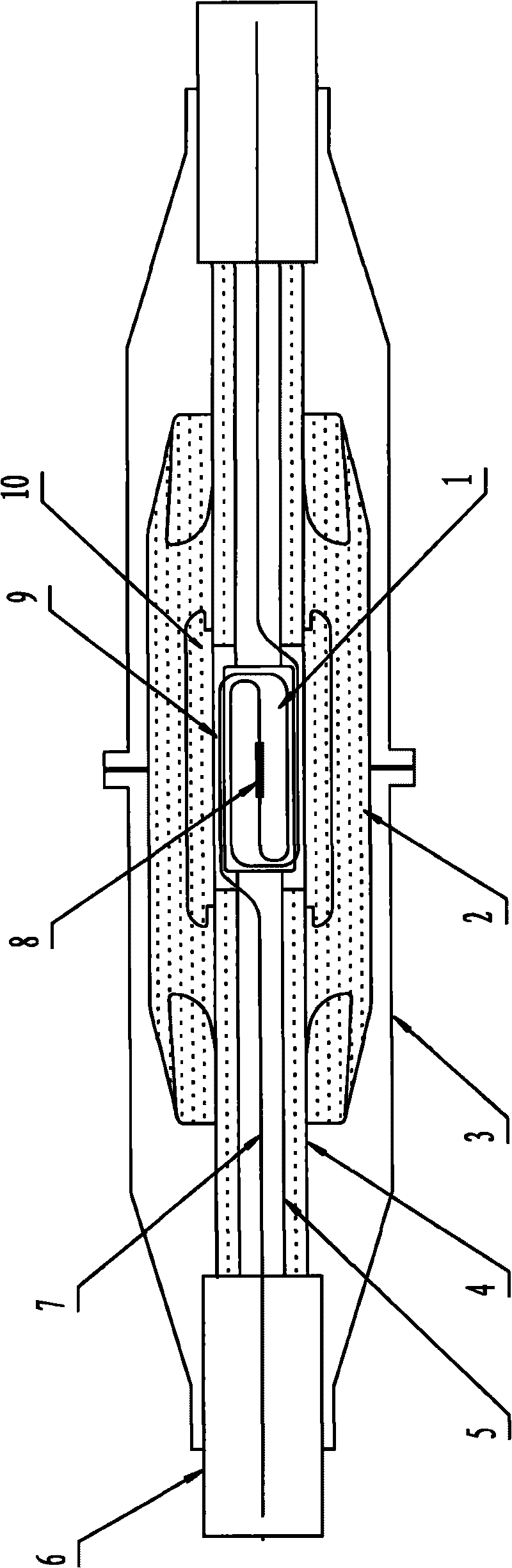
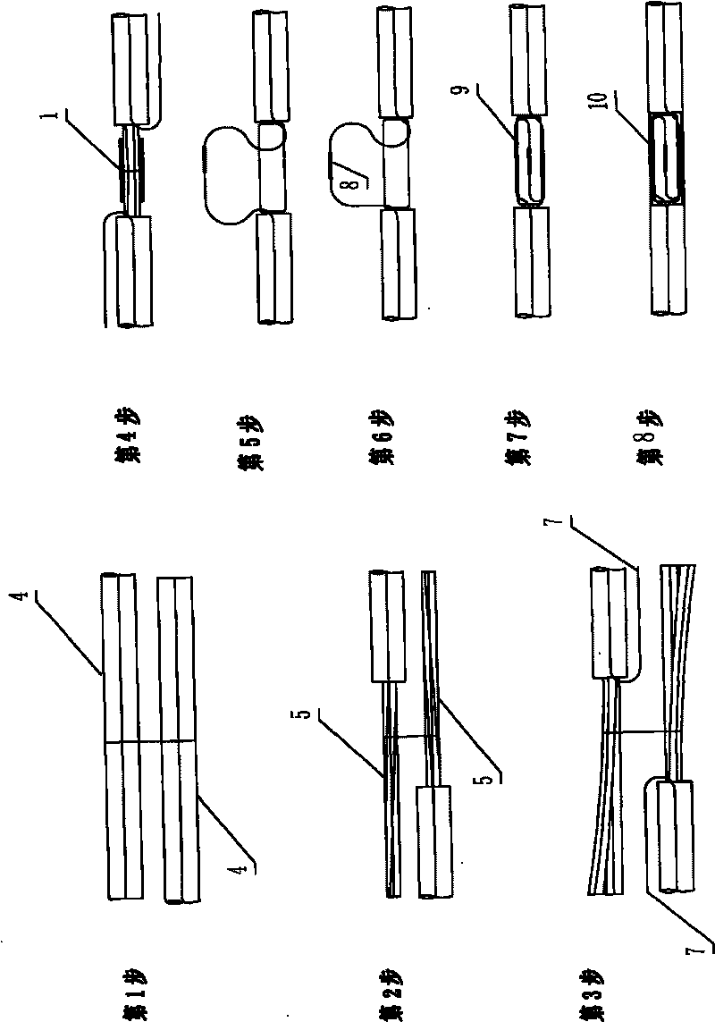
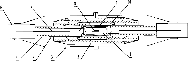
[0021] according to Figure 1~2 The specific implementation steps of the present invention will be described in detail. The application of the composite power cable connection box with optical fiber in the conductor center is specially used for the composite power cable with optical fiber in the conductor center. , a semicircular optical fiber splice box 9, and a connection box made of a protective cover 10.

[0022] The composite power cable in which the optical fiber is arranged in the center of the conductor in this embodiment adopts the "method for stranding the optical fiber in the conductor center of the composite power cable" by the inventor, and is processed by existing equipment and a commonly used cable stranding process in line with the existing Products specified in the standards for ultra-high voltage XLPE insulated power cables. To put it simply, the composite power cable with a cross-section of more than 800 square millimeters and an optical fiber in the cente...


PUM


Abstract

The invention relates to an application of a composite power cable connection box with an optical fiber arranged in the center of a conductor. The application has the operation steps of: setting the reserved length of a cable, exposing the core of the cable, splitting a round cable split conductor and leading out the optical fiber with a stainless steel jacket from a gap between two fan-shaped conductor units; after cutting off a part of the round cable split conductor, connecting the optical fiber with a cable conductor connecting pipe; carrying out optical fiber welding outside the cable conductor connecting pipe so as to regularly coil and fix the optical fiber in a half-round optical fiber joint box; and then carrying out other operations of the connection box. The invention solves the problems that great effort needs to be taken to move the optical fiber, the temperature measurement of joints is not accurate, and the like of the traditional connecting process; in addition, the invention has reasonable connecting process, easy site construction and simple and quick operation, can meet the automatic monitoring requirements on on-line real-time temperature detection, aging monitoring, and real-time fault monitoring and early warning of the safe operation of a power cable line, can carry out normal cable and optical fiber connecting operations at a construction site, obviously improve the reliability and the efficiency of construction works and reduce the construction cost.

Description

technical field [0001] The invention relates to a connection method of a connection box for XLPE insulated power cable lines. In particular, the application of a composite power cable connection box with an optical fiber in the center of the conductor, which is mainly used for multi-section composite power cables in which the temperature-measuring optical fiber is directly placed in the center of the twisted circular split conductor, and is connected through a special connection box. The required power cable routing. Background technique [0002] With the development and application of distributed optical fiber sensing technology, in order to ensure the safe operation of the transmission of strong electric energy in the power cable line, the power department requires the use of temperature measuring optical fiber to carry out the following automatic monitoring of the safe operation of the cables in the entire line: 1. Online real-time temperature detection, in order to moni...

Claims


Application Information

Patent Timeline
IPC IPC(8): H02G15/10G02B6/36
Inventor 吕庚民
Owner SHENYANG FURUKAWA CABLE
Why Eureka
Try Eureka