Directional punching shear and processing method for iron core pieces of stator and rotor of rotary motor

A technology of rotating electrical machines and processing methods, which is applied in the manufacture of stator/rotor bodies, etc., and can solve problems such as uneven mold gaps, small punching and shearing forces, and high concentricity of iron chips

Active Publication Date: 2010-06-02
陈石云
View PDF0 Cites 12 Cited by
  • Summary
  • Abstract
  • Description
  • Claims
  • Application Information

AI Technical Summary

Problems solved by technology

This method of positioning only on the circular surface is equal to only the center of the circle and not the circumference orientation (that is, the centering is not oriented). The result: due to mold manufacturing errors, punching shear force, mold deformation, uneven mold clearance, wear, The direction of the different rolling marks of the material (please refer to page 98 of the "Stamping Sub-volume" of the "Forging Handbook" edited by Li Shuoben published in 2002 figure 2 .2.18 Regarding the influence of the rolling direction on the dimensional deviation), etc., the dimensional deviations of different orientations of the blank sheets are different, resulting in dislocation of the iron core on the outer or inner side of the iron core, and the appearance is ugly
Although the said scheme has a simple mold with high processing precision, high concentricity of the inner and outer circles of a single iron chip, small punching and shearing force, and is convenient for automatic feeding, it cannot be widely used due to its shortcomings.

Method used


Image

  • Directional punching shear and processing method for iron core pieces of stator and rotor of rotary motor
  • Directional punching shear and processing method for iron core pieces of stator and rotor of rotary motor
  • Directional punching shear and processing method for iron core pieces of stator and rotor of rotary motor

Examples


specific Embodiment

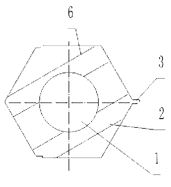
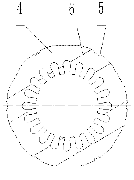
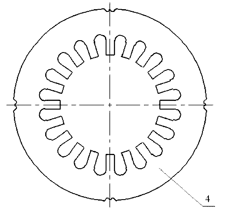
[0023] refer to Figure 1 to Figure 9 , a method for directional punching and shearing processing of stator and rotor core sheets of a rotating electrical machine, characterized in that: firstly, punching an annular blank sheet 2 of the stator core with a rotor mounting through hole 1 in the middle, and the annular blank sheet 2 is provided with The positioning mark 3 of the rotation orientation is used for forming between the annular blank sheet 2 and the punch mold according to the determined rotation orientation during molding, and the positioning mark 3 is used to limit the ring blank sheet 2 and the punch mold when the blank sheet 2 is formed. Rotation orientation between, and limit the rotation orientation of annular blank sheet 2 between annular blank sheet 2 and punching die of stator iron sheet when stator iron sheet 4 is formed simultaneously, on the stator iron sheet 4 of described molding Marks 5 are made for the correct splicing of the stator core sheets of the sa...


PUM


Abstract

The invention discloses a directional punching shear and processing method for the iron core pieces of a stator and a rotor of a rotary motor, which is characterized in that the annular blank pieces of the iron cores of the stator, the middle part of which is provided with an installation through hole of the rotor are firstly punched and are provided with a positioning mark of a rotating orientation, the positioning mark of the rotating orientation is used for forming the annular blank pieces and a punch mould according to a preset rotating orientation during forming, and a mark which is used for correctly overlapping the iron core pieces of the same stator is manufactured on the formed iron core pieces of the stator after the iron core pieces of the stator are formed.The invention aims to provide the directional punching shear and processing method for the iron core pieces of the stator and the rotor of the rotating motor. The method effectively solves the problem of size deviation of the iron core pieces caused by different cutting edges of the mould and the problem of dislocation of the inner edges and the outer edges of the iron cores caused by the size deviation of the iron core pieces caused by different orientations of the rolling traces of materials and improves the appearance of the iron cores greatly.

Description

technical field [0001] The invention relates to a directional punching and shearing processing method for stator and rotor iron chips of a rotating electrical machine, which is suitable for the processing industry of the stator and rotor iron chips of the rotating electrical machine in the field of motors. Background technique [0002] At present, there are many methods for forming the core sheet, one of which is to first form the stator core blank sheet for forming the stator core sheet, and the stator core blank sheet is formed into a ring with the same inner and outer diameters as the iron sheet. Then, use the inner round hole of the stator core blank sheet to locate and cut off the slot and use for superimposed positioning between iron chips, fastening structure and other redundant materials. This method of positioning only on the circular surface is equal to only the center of the circle and not the circumference orientation (that is, the centering is not oriented). The...

Claims


Application Information

Patent Timeline
Patent Type & Authority Applications(China)
IPC IPC(8): H02K15/02
Inventor 陈石云
Owner 陈石云
Why Eureka
Try Eureka