

Vertical milling lathe complex machining center
A composite machining center, vertical milling technology, applied in metal processing equipment, metal processing mechanical parts, manufacturing tools, etc., to achieve the effect of reducing costs, stable clamping, and improving equipment life
- Summary
- Abstract
- Description
- Claims
- Application Information
AI Technical Summary
Problems solved by technology
Method used
Image

Examples
Embodiment Construction
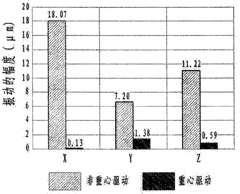
[0021] Image 6 It is a comparison diagram of the vibration amplitude of the single-axis turntable of the present invention and the turntable driven by the non-center of gravity.
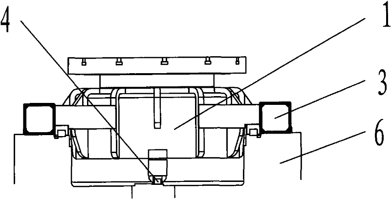
[0022] Such as Figure 4 As shown, the direct-drive external rotor torque motor used in the vertical milling and turning compound machining center of the present invention includes a torque motor stator 111, a rotor 110, a clamping device 109 for braking, a motor cooling device for cooling, and a pendulum Other auxiliary structures used in the head, such as encoder 103, encoder bracket 101, spindle box 102, turning and milling spindle 104, bearing gland 105, turntable bearing 106, bearing housing 107, housing 108, base plate 112, etc.
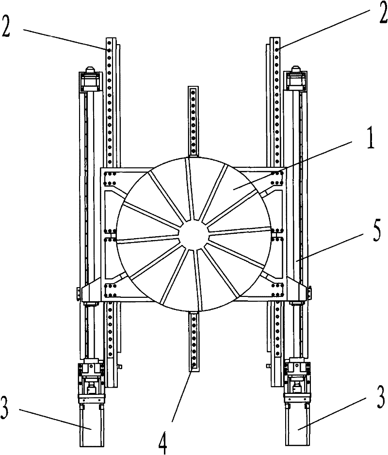
[0023] Such as image 3 The structure of the vertical milling-turning compound machining center shown in the present invention includes a bed 6 arranged horizontally, and two columns 7 arranged on one side of the bed 6 vertically. The bed 6 is provided with two ro...
PUM
 Abstract
Description
Claims
Application Information