
Plastic bottle pipe heater feed delivering device

A heater and plastic bottle technology, applied in the field of plastic machinery, can solve the problems of bottle tubes and tube jams, etc., and achieve the effects of accurate positioning, accurate tube feeding, and reliable action

Inactive Publication Date: 2012-09-26
林明茳
View PDF0 Cites 0 Cited by
  • Summary
  • Abstract
  • Description
  • Claims
  • Application Information

AI Technical Summary

Problems solved by technology

But in order to make the plastic bottle tubes can enter between each positioning friction wheel, the spacing of each plastic bottle tubes must be evenly arranged when the tubes are fed. The tubes slide from top to bottom, and the tubes are crowded together into the tubes, which cannot realize the spacing of each bottle tube and evenly enter the operation between the positioning friction wheels
And the plastic bottle tube sliding down the ramp may get stuck at the connection between the ramp exit and the heater inlet due to insufficient sliding force, causing the tube to get stuck, so that the bottle tube cannot enter the heater for heating

Method used


Image

  • Plastic bottle pipe heater feed delivering device
  • Plastic bottle pipe heater feed delivering device
  • Plastic bottle pipe heater feed delivering device

Examples


Embodiment Construction

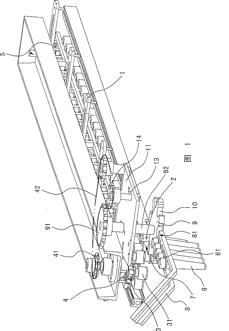
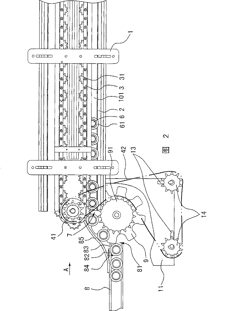
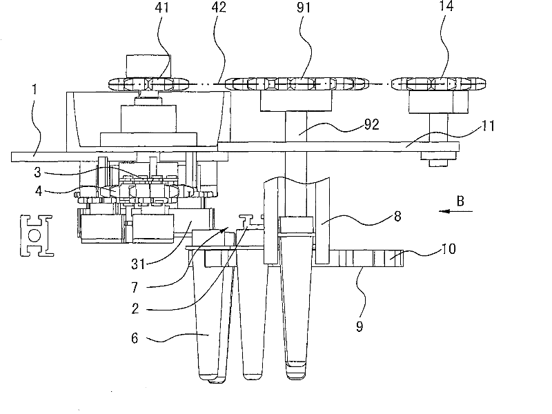
[0012] The invention relates to a plastic bottle tube heater feeding device, such as Figure 1-Figure 6 As shown, it includes a bottle tube heater, and the inlet of the bottle tube heater is connected to the bottle tube feeding mechanism. The bottle tube heater includes a frame 1, a bottle tube conveying channel 101 is arranged in the frame, and a bottle tube conveying channel 101 is arranged. One side is the transmission chain 3 installed on the frame 1, the other side of the bottle tube conveying path is the rack 2 installed on the frame 1, and the transmission chain 3 is driven by the driving wheel 4 and the driven wheel 5 for circular motion. , the positioning friction wheel 31 is installed in the transmission chain 3, and the positioning friction wheel 31 stretches between each plastic bottle tube 6 and contacts with the plastic bottle tube 6 heads, and drives the plastic bottle tube 6 to run, and the baffle plate 61 of the plastic bottle tube 6 Placed on the rack 2, the ...


PUM


Abstract

The invention relates to a plastic bottle pipe heater feed delivering device which comprises a heater, wherein an inlet of the heater is connected with a bottle pipe feed mechanism; the heater comprises a frame, and a delivering passage is arranged in the frame; one side of the delivering passage is provided with a drive chain which is installed on the frame, and the other side of the delivering passage is provided with a placing bar which is installed on the frame; the drive chain does annular motion by a drive wheel and a driven wheel which are driven by power; a positioning friction wheel is installed in the drive chain, extends among all plastic bottle pipes to be in contact with the heads of the plastic bottle pipes and drives the bottle pipes to run; a baffle plate of the bottle pipes is placed on the placing bar; and the feed mechanism comprises a pipe delivering slideway which is connected with an inlet of a bottle pipe heater and a plastic bottle pipe delivering device. The bottle pipe delivering device is characterized by comprising a delivering disk which is installed between the pipe delivering slideway and the inlet of the bottle pipe heater; the edge of the delivering disk is provided with delivering teeth, and the delivering teeth are in contact with the plastic bottle pipes; the delivering disk is driven to rotate by a drive mechanism, and an outlet of the pipedelivering slideway is provided with a pipe clamping prevention device and a pipe release preventing device.

Description

technical field [0001] The invention relates to a plastic bottle tube heater, in particular to a tube feeding device for the plastic bottle tube heater, and belongs to the field of plastic machinery. Background technique [0002] In the production of hollow plastic containers, such as processing mineral water bottles, oil bottles, cosmetic bottles, etc., the plastic raw materials are first injected into bottle tubes by injection molding machines, and then the plastic bottle tubes are heated by a heater, and then heated by a stretch blowing machine. Bottle tube stretch blow molding. The vast majority of existing plastic bottle tube heaters insert the bottle tube on the support base, and the support base is driven by a chain or slider to heat the bottle tube through the heating zone. The disadvantage of this technology is not only the machine structure It is complicated, and more importantly, if it is combined with a stretch-blow machine, there are many sets of feeding or unl...

Claims


Application Information

Patent Timeline
Patent Type & Authority Patents(China)
IPC IPC(8): B29C49/42B29C49/64B29C31/08B29L22/00
Inventor 林明茳
Owner 林明茳
Learn More