Energy collection and conversion

A kinetic energy and potential energy technology, applied in machines/engines, mechanical equipment, mechanisms that generate mechanical power, etc., can solve problems such as high maintenance costs, small scope of application, and large investment income ratio

Inactive Publication Date: 2010-06-09
翟爱民 +1
View PDF3 Cites 20 Cited by
  • Summary
  • Abstract
  • Description
  • Claims
  • Application Information

AI Technical Summary

Problems solved by technology

[0002] The existing method of collecting and converting kinetic energy and potential energy of water has huge equipmen

Method used


Image

  • Energy collection and conversion
  • Energy collection and conversion
  • Energy collection and conversion

Examples


Embodiment Construction

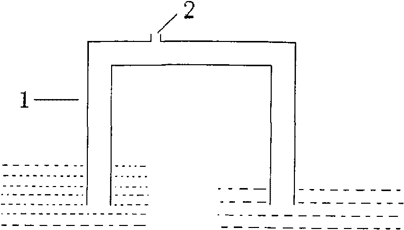
[0007] Such as figure 1 Shown: the water flow in the inverted U-shaped pipe 1 is turbulent, when the water flow passes through the inverted U-shaped pipe 1, the part above the water surface is under negative pressure, and there is an air inlet on the inverted U-shaped pipe 1 above the water surface 2. Gas enters the inverted U-shaped tube 1 automatically from the air inlet 2, and is separated into small bubbles and transported away with the water flow. Adjust the intake volume so that the water flow will not be interrupted, and there is a continuous negative pressure airflow for use at the intake hole 2, so as to obtain the air pressure difference energy.

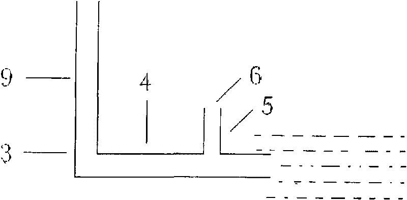
[0008] Such as figure 2 Shown: the water flow in the L-shaped pipe 3 is a turbulent flow. After the air-bubble-containing water flows through the vertical pipe 9 of the L-shaped pipe 3 and enters the horizontal pipe 4 under the liquid surface, the air bubbles will float up and pass through the horizontal pipe 4. The exha...


PUM


Abstract

The invention relates to energy collection and conversion technology for kinetic energy and potential energy stored in water. The technology converts the kinetic energy and the potential energy stored in the water into atmospheric pressure difference energy by utilizing that bubbles can move to ideal positions along with the waterflow when the bubbles are separated to be small to a certain extent by the waterflow in turbulent water. After the bubble-containing waterflow flows through a vertical pipe (9) of an L-shaped pipe (3) and then enters a traverse pipe (4), the bubbles can float upward and are discharged through an exhaust port (6) of a collection pipe (5) on the traverse pipe (4). The air displacement is adjusted to ensure that the waterflow cannot be interrupted, and the continuous positive pressure airflow for the utilization is produced at the exhaust port (6). The technology that the kinetic energy and the potential energy stored in the water are collected and converted into the atmospheric pressure difference energy, and then are converted into available energy sources by utilizing the characteristics that the atmospheric pressure difference energy is easy to convey and convert into other energy sources (for example, other technology is combined to pump the water to high positions or generate the electricity and the like without consuming oil and electricity) has the advantages of small needed equipment, high energy conversion rate, small cost-benefit ratio, wide applicable range, and basic maintenance-free performance.

Description

Technical field: [0001] The invention relates to a collection and conversion technology of kinetic energy and potential energy of water accumulation. Background technique: [0002] The existing method for collecting and converting kinetic energy and potential energy of water has huge equipment, low energy conversion rate, high return on investment ratio, small scope of application, and high maintenance costs. Invention content: [0003] The invention designs a method for conveniently collecting the kinetic energy and potential energy accumulated by water and converting them into air pressure difference energy for further utilization. In order to solve the above problems, the technical solution adopted by the present invention is: in turbulent water, the bubbles separated by the water flow are small to a certain extent, and the bubbles will move with the water flow and can be transported to the ideal place for collection. In this way, the kinetic energy and potential energ...

Claims


Application Information

Patent Timeline
IPC IPC(8): F03G7/00
Inventor 翟爱民
Owner 翟爱民
Why Eureka
Try Eureka