Gas supply device of multi-tube non-wheel pump

A technology of air supply device and air collecting device, which is applied to pumps, pressure pumps, non-displacement pumps, etc., can solve the problems of large investment income ratio, low energy conversion rate, and small application scope, and achieves a small investment income ratio, The effect of high energy conversion rate and wide application range

Inactive Publication Date: 2015-10-14
BEIJING SHUICHUANGXINNENG TECH CO LTD
View PDF4 Cites 2 Cited by
  • Summary
  • Abstract
  • Description
  • Claims
  • Application Information

AI Technical Summary

Problems solved by technology

[0003] The reserves of water conservancy energy are very rich, and it is one of the important ways of energy development and utilization, and it has very significant advantages such as cleanliness and recirculation. Kinetic energy and potential energy are rotated into mechanical energy to obtain electricity. In this way, a large amount of water conservancy infrastructure and supporting special hydroelectric generator sets are required. The one-time investment in the early stage is quite large, which has certain adverse effects on the environment, especially hydroelectric power generation. The unit structure is complex, the equipment is huge, the energy conversion rate is low, and it is also prone to failures and problems. Therefore, it needs to be improved and optimized
[0004] Existing pumping technology requires high-cost energy such as manpower and electricity to pump river water and canal water with a high velocity to high places; the technology using liquid energy requires huge equipment, low energy conversion rate, and large investment-to-income ratio, which is suitable for Small range, high maintenance cost
[0005] In addition, the use of water conservancy energy, and the method of using water hammer pumps to obtain a higher water head, there are also many unfavorable factors such as large investment and low efficiency.

Method used


Image

  • Gas supply device of multi-tube non-wheel pump
  • Gas supply device of multi-tube non-wheel pump
  • Gas supply device of multi-tube non-wheel pump

Examples


Embodiment 1

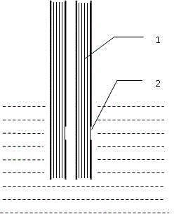
[0029] For embodiment one, the common basic structure is as figure 1 Shown: the main structure is mainly made up of thin tube A1, and one end of thin tube A1 is connected to the atmosphere outside the liquid surface. ) below the liquid surface, figure 1 The corrugated lines in the figure represent liquid (the same below), the uppermost one represents the liquid level, and the narrow tube A1 has an air inlet A2 on a section below the liquid level, and is connected with pressurized gas, and the pressure of the pressurized gas is equal to the atmospheric pressure. The difference is A, that is, the pressure of the pressurized gas is stronger than the air pressure, and the large value is A. The measurement unit of A is the height value in the thin tube of the liquid, and the height difference from the air inlet A2 to the liquid surface is less than or Far less than the height of the water column whose pressure is equal to the A value generated by the pressurized gas, that is, th...

Embodiment 2

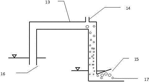
[0032] For example two, such as figure 2 As shown: one end of the thin tube B3 is under the liquid surface; the other end is outside the liquid surface, and it is connected to the negative pressure container B4. There is an air extraction hole B41 on the negative pressure container B4, which can be connected to the negative pressure air source. Inside the negative pressure container B4 The difference between the pressure of the negative pressure gas and the atmospheric pressure is B, that is to say, the pressure of the negative pressure gas is smaller than the atmospheric pressure, and the small quantity value is B, and the measurement unit of B is the height value in the capillary of the liquid. On the thin tube B3 section outside the liquid surface, an air inlet B5 is set to lead to the atmosphere. The height difference between the air inlet B5 and the liquid surface is less than or much smaller than the height of the water column whose pressure is equal to the B value gene...


PUM


Abstract

The invention relates to a gas supply device of a multi-tube non-wheel pump. According to the main technical scheme adopted by the invention, the gas supply device is characterized by being an inverted-U-shaped tube gas collecting device, wherein an inverted-U-shaped tube is provided with a water inlet and a water outlet; the water inlet is positioned in the liquid surface of a water source; the water outlet is positioned in the liquid surface of a water-release water path; the pipeline diameter of the water outlet is greater than that of the water inlet; the gas inlet is arranged on the pipeline wall, higher than the liquid surface of a water inlet water source, of a transverse tube of the inverted-U-shaped tube; and the water outlet is also the gas outlet; and the gas inlet is positioned at one end, close to the low water level, of the transverse tube of the inverted-U-shaped tube. The gas supply device of the multi-tube non-wheel pump can generate gas pressure differential energy which can be used as an energy source for transporting water to a high position or a predetermined position.

Description

[0001] This patent application is a divisional case of the patent application submitted to the China Patent Office on June 22, 2010, the application number is 201010205155.0, and the invention name is "Multiple Tube Regardless Pump". The relevant content is incorporated in this patent application by reference. technical field [0002] The invention relates to a method for collecting liquid energy, in particular to a multi-tube non-wheel pump air supply device, which is a method and device for conveniently collecting kinetic energy and potential energy contained in liquid and converting them into pressure difference energy for further utilization . Background technique [0003] The reserves of water conservancy energy are very rich, and it is one of the important ways of energy development and utilization, and it has very significant advantages such as cleanliness and recirculation. Kinetic energy and potential energy are rotated into mechanical energy to obtain electricity....

Claims


Application Information

Patent Timeline
Patent Type & Authority Applications(China)
IPC IPC(8): F04F1/06
Inventor 翟爱民
Owner BEIJING SHUICHUANGXINNENG TECH CO LTD
Why Eureka
Try Eureka