Electronic component and manufacturing method thereof
A technology of electronic components and manufacturing methods, which is applied in the manufacture of inductors/transformers/magnets, electrical components, circuits, etc., can solve the problems of large-scale winding electronic components, and achieve the effect of reducing the height and suppressing the protrusion of the eaves.
- Summary
- Abstract
- Description
- Claims
- Application Information
AI Technical Summary
Problems solved by technology
Method used
Image

Examples
no. 1 approach
[0034] Structure of Coil Parts
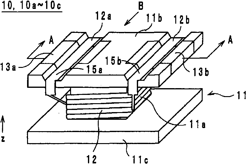
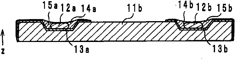
[0035] The configuration of the coil component according to the first embodiment will be described with reference to the drawings. figure 1 It is an external perspective view of the coil component 10, 10a-10c which concerns on embodiment. figure 2 is along figure 1 A-A cross-sectional structural diagram of the coil component 10 of FIG. exist figure 1 and figure 2 In , the direction in which the coil axis extends is defined as the z-axis direction.
[0036] like figure 1 As shown, the coil component 10 includes a core 11, a lead wire (wire) 12, and electrodes 13a, 13b. The core 11 is made of insulating materials such as ferrite, aluminum oxide, etc., and includes a core 11a ( figure 1 Covered by leads 12) and eaves 11b, 11c.
[0037] like figure 1 As shown, the core 11a is a prism-shaped member extending in the z-axis direction. However, the core 11a is not limited to a prism shape, and may be a cylindrical shape or a polygonal...
no. 2 approach
[0054] Next, the coil component and its manufacturing method according to the second embodiment will be described with reference to the drawings. quote figure 1 It is an external perspective view of the coil component 10a which concerns on 2nd Embodiment. Figure 5 It is A-A cross-sectional structure drawing of the coil component 10a concerning 2nd Embodiment. exist figure 1 and Figure 5 In , the direction in which the coil axis extends is defined as the z-axis direction.
[0055] The difference between the coil component 10 and the coil component 10a is that, as figure 2 and Figure 5 As shown, in the coil component 10, the flat portions 12a, 12b are covered with the solder layers 14a, 14b, whereas in the coil component 10a, the flat portions 12a, 12b are not covered with the solder layers 14a, 14b. Specifically, in coil component 10a, solder layers 14a, 14b are provided to cover electrodes 13a, 13b. Then, the flat portions 12a, 12b are provided on the solder layer...
no. 3 approach
[0059] Next, a coil component and a manufacturing method thereof according to a third embodiment will be described with reference to the drawings. quote figure 1 It is an external perspective view of a coil component 10b according to the third embodiment. Image 6 It is A-A cross-sectional structure drawing of the coil component 10b which concerns on 3rd Embodiment. exist figure 1 and Image 6 In , the direction in which the coil axis extends is defined as the z-axis direction.
[0060] The difference between the coil component 10a and the coil component 10b is that, in the coil component 10a, such as Figure 5 As shown in FIG. Image 6As shown, the flat parts 12a, 12b having a semicircular cross-sectional structure are formed by cutting the lead wire 12 . In addition, since the other configurations of the coil component 10b are the same as those of the coil component 10a, description thereof will be omitted. Also in the coil component 10b having the above-mentioned s...
PUM
 Abstract
Description
Claims
Application Information
 - R&D
- Intellectual Property
- Life Sciences
- Materials
- Tech Scout
- Unparalleled Data Quality
- Higher Quality Content
- 60% Fewer Hallucinations
Browse by: Latest US Patents, China's latest patents, Technical Efficacy Thesaurus, Application Domain, Technology Topic, Popular Technical Reports.
© 2025 PatSnap. All rights reserved.Legal|Privacy policy|Modern Slavery Act Transparency Statement|Sitemap|About US| Contact US: help@patsnap.com