
Oil evacuation and nitrogen injection control device of oil-immersed transformer

A technology of oil-immersed transformers, oil discharge and nitrogen injection, which is applied in transformer/inductor cooling, program control, computer control, etc., can solve the problem of inability to realize information management and remote monitoring and operation, being easily affected by environmental temperature changes, It is not convenient for equipment maintenance and accountability, and achieves the effect of facilitating program modification and supplementary functions, improving reliability and maintainability, and facilitating archiving and analysis

Inactive Publication Date: 2010-06-09
深圳市旭明消防设备有限公司
View PDF0 Cites 8 Cited by
  • Summary
  • Abstract
  • Description
  • Claims
  • Application Information

AI Technical Summary

Problems solved by technology

[0009] Relay control uses hard wiring to implement logic. Once the logic function is determined, it is very difficult to modify or add functions.
[0010] Relays control many electric shocks, which will cause mechanical wear and arc burns, and the wiring will increase accordingly, resulting in poor reliability and maintenance performance
[0011] The timing accuracy of the time relay is not high, it is easily affected by the change of ambient temperature, and it has no counting function
[0012] It does not have the recording function of fault alarm and personnel operation, which is not convenient for equipment maintenance and accountability
[0013] The relay control method does not have network functions, and cannot realize information management and remote monitoring and operation

Method used


Image

  • Oil evacuation and nitrogen injection control device of oil-immersed transformer
  • Oil evacuation and nitrogen injection control device of oil-immersed transformer
  • Oil evacuation and nitrogen injection control device of oil-immersed transformer

Examples


Embodiment Construction

[0028] Embodiments of the present invention will be described in detail below in conjunction with the accompanying drawings.

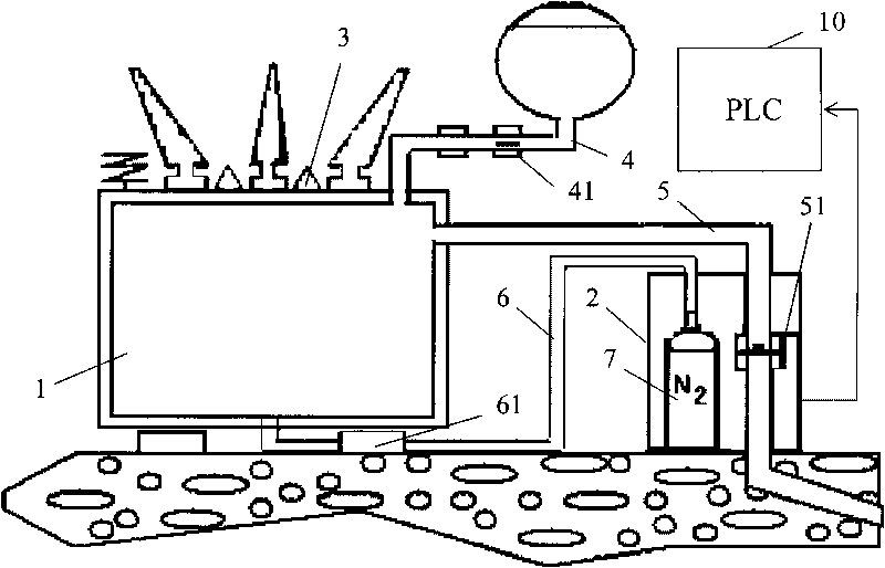
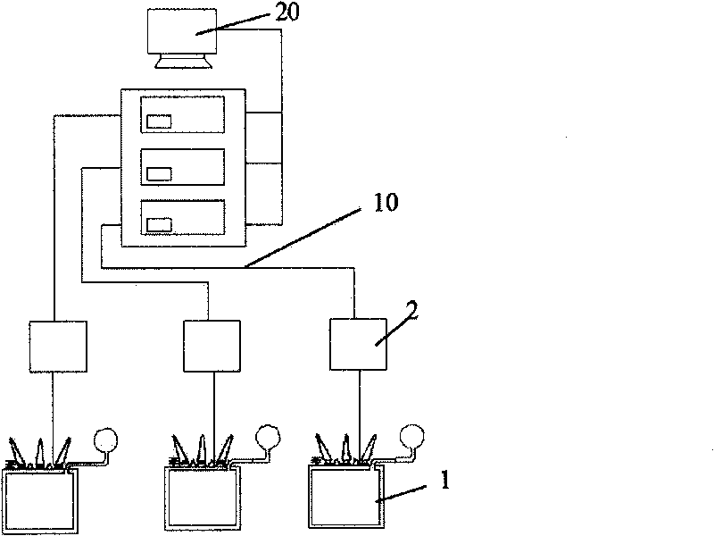
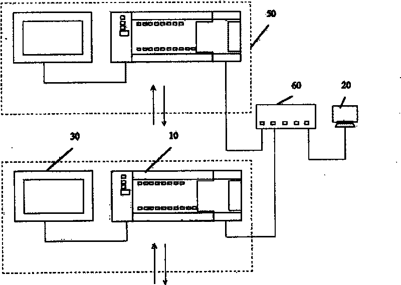
[0029] Such as figure 1 Shown is a schematic structural view of the first embodiment of the oil discharge and nitrogen injection control device of the present invention, which includes: an on-site detector 3, an oil drain valve 51, a shut-off valve 41 and a nitrogen inlet valve 61, and the on-site detector 3 is set On the oil-immersed transformer 1, the oil drain valve 51 is arranged on the oil discharge pipeline 5, the shut-off valve 41 is arranged on the oil inlet pipeline 4, and the nitrogen inlet valve 61 is arranged on the nitrogen inlet pipeline 6. 3 The detected signal controls the PLC (programmable logic controller) 10 for the action of the oil drain valve 51, the shut-off valve 41 and the nitrogen inlet valve 61, the on-site detector 3, the oil drain valve 51, the shut-off valve 41 and the nitrogen inlet valve The valve 61 is electrically con...


PUM


Abstract

The invention discloses an oil evacuation and nitrogen injection control device of an oil-immersed transformer, which comprises an on-site probe, an oil-release valve, a cut-off valve and a nitrogen inlet valve, wherein the on-site probe is arranged on the oil-immersed transformer, the oil-release valve is arranged on an oil drain pipeline, the cut-off valve is arranged on an oil inlet pipeline, a nitrogen inlet valve is arranged on a nitrogen inlet pipeline, and the oil evacuation and nitrogen injection control device is characterized in that the oil evacuation and nitrogen injection control device further comprises a PLC which controls the oil-release valve, the cut-off valve and the nitrogen inlet valve to act according to a signal obtained according to the detection of the on-site probe, and the on-site probe, the oil-release valve, the cut-off valve and the nitrogen inlet valve are electrically connected with the PLC. The oil evacuation and nitrogen injection control device adopts the PLC for controlling, thereby being stable and reliable, realizing convenient operation and high maintainability and better ensuring the safety of the use of the oil-immersed transformer.

Description

technical field [0001] The invention relates to the field of electric fire prevention and fire extinguishing, in particular to an oil discharge and nitrogen injection control device for an oil-immersed transformer. Background technique [0002] Power transformers are one of the most important equipment in power plants and substations. Oil-immersed transformers are the most commonly used. Due to their own structure, insulating materials used and operating conditions of transformers, oil-immersed transformers have hidden dangers of fire accidents. Transformer explosion and fire are generally caused by internal insulation damage. The reasons are: overload, operating overvoltage, lightning overvoltage, gradual aging of insulation, damp of transformer oil or decline in insulation level of oil acidification, etc. Once the insulation breakdown causes an arc, the temperature and pressure of the oil will increase sharply, and the pressure in the tank will rise sharply. After mixing ...

Claims


Application Information

Patent Timeline
Patent Type & Authority Applications(China)
IPC IPC(8): H01F27/14G05B19/048
Inventor 刘荣军张永才
Owner 深圳市旭明消防设备有限公司
Learn More