Unlock instant, AI-driven research and patent intelligence for your innovation.

Electric connection box and assembling method for electric connection box

A technology for electrical connection boxes and electrical components, which is applied in substation/distribution device shells, electrical components, etc., which can solve the problems of reduced mounting surface and inability to support the shell stably, and achieve the effect of suppressing position deviation

Inactive Publication Date: 2010-06-09
SUMITOMO WIRING SYST LTD
View PDF1 Cites 2 Cited by
  • Summary
  • Abstract
  • Description
  • Claims
  • Application Information

AI Technical Summary

Problems solved by technology

In addition, as described above, if there is an identification mark portion protruding from the case surface in the vacant space at the peripheral portion of the case surface, the identification mark portion cannot be mounted on the mounting table portion 111 of the assembling jig. However, it is necessary to change the shape of the mounting table to avoid the protruding identification mark, so there is a problem that the mounting surface of the housing on the mounting table 111 is reduced and the housing cannot be stably supported.

Method used


Image

  • Electric connection box and assembling method for electric connection box
  • Electric connection box and assembling method for electric connection box
  • Electric connection box and assembling method for electric connection box

Examples


Embodiment Construction

[0029] Embodiments of the present invention will be described below with reference to the drawings.

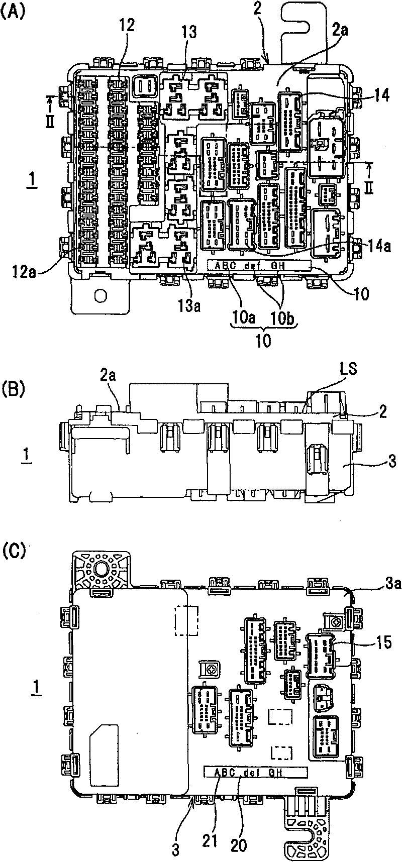
[0030] figure 1 The electrical connection box of the illustrated embodiment is mounted on an automobile, and the upper casing 2 and the lower casing 3 are locked and connected to form a casing of the electrical connection box 1 .

[0031] Such as figure 2 As shown, inside the casing composed of the upper casing 2 and the lower casing 3, the lower printed circuit board 7, the insulating plate 6, the upper printed circuit board 5, and the insulating sheet 8 are stacked in order from the side of the lower casing 3. , the bus bar 9 is directly fixed on the inner surface of the upper casing 2 .

[0032] The electrical junction box is assembled as image 3 As shown, on the mounting table portion 52 protruding from the lower end inner peripheral surface of the outer peripheral frame 51 of the assembly jig 50 and provided in a substantially frame shape, the above-mentioned upper ...


PUM


Abstract

The invention provides an electric connection box and an assembling method for the electric connection box, wherein the identifying mark portion disposed on the housing surface of the electric connection box can be used as the clip loading surface loaded on the clip for assembling during the assembling of the electric connection box. An installation portion of electric parts is disposed as projecting from the reference surface of the housing surface, and an identification mark portion (11) is provided along the peripheral portion of the housing surface, the identification mark portion (11) makes the marking portion (10) protrude from the concave portion bottom depressed from the reference surface (LS) of the housing surface to form the shape of relief sculpture, and the surface (10S) protruding from the marking portion is located at the same height of the reference surface (LS) of the housing. The identifying mark portion is the clip loading surface (X3) which is abutted against during clip assembling.

Description

technical field [0001] The present invention relates to an electrical connection box and an assembly method of the electrical connection box. Specifically, when sequentially inserting internal circuit components into a housing of a vehicle-mounted electrical connection box and assembling, the identification mark part is realized as being supported by an assembly jig. Effective use of the loading surface. Background technique [0002] Conventionally, an identification mark portion indicating a manufacturer's name and a product number has been provided on the casing surface of the electrical junction box. This identification mark portion is displayed using large characters or the like so that it can be recognized clearly at a glance. [0003] As described in Japanese Patent Application Laid-Open No. 11-225418 (Patent Document 1), the identification mark part is sometimes an attached display label, but since there is a problem that the label is easy to peel off, as in Figure ...

Claims


Application Information

Patent Timeline
Patent Type & Authority Applications(China)
IPC IPC(8): H02G3/16H02B1/26
Inventor 宫本隆司
Owner SUMITOMO WIRING SYST LTD
Features
  • R&D
  • Intellectual Property
  • Life Sciences
  • Materials
  • Tech Scout
  • Unparalleled Data Quality
  • Higher Quality Content
  • 60% Fewer Hallucinations
Learn More