Suction cleaner

A technology of vacuum cleaners and filters, applied in the directions of vacuum cleaners, cleaning equipment, household appliances, etc., can solve the problems of not being able to cool the motor and circuit board, affecting normal use, and easy to heat the motor and circuit board, so as to prolong the service life and avoid Simple and reasonable structure of overheating and air cooling

Inactive Publication Date: 2010-06-16
沈建明
View PDF1 Cites 6 Cited by
  • Summary
  • Abstract
  • Description
  • Claims
  • Application Information

AI Technical Summary

Problems solved by technology

Its structural design is unique in many places, but the fly in the ointment is that the fan blade of the motor adopts a simple structure fan blade, which generally can only guide the airflow from the inlet of the cavity to the rear air outle

Method used


Image

  • Suction cleaner
  • Suction cleaner
  • Suction cleaner

Examples


Example Embodiment

[0016] The present invention will be further described in detail below with reference to the embodiments of the accompanying drawings.

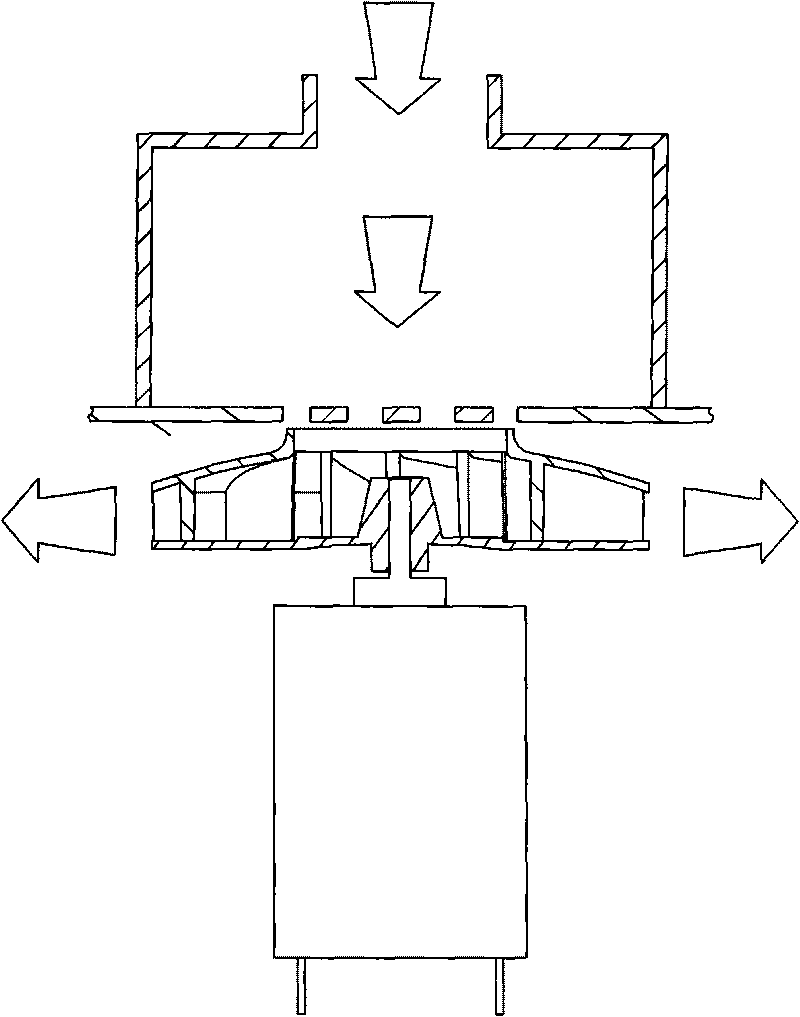
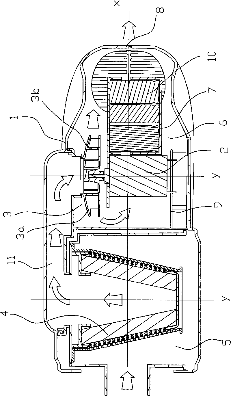
[0017] As shown in the figure, the horizontal direction described in this article is the X-axis, and the vertical direction is the Y-axis, and the schematic diagram shall prevail. This vacuum cleaner includes main components such as a casing 1, a motor 2, a fan blade 3, a filter 4, etc. The front part of the casing 1 is a dust collection and separation chamber 5, the rear part of the casing is a cavity 6, and the rear part of the casing 1 The motor 2 is arranged in the inner cavity 6 through the motor frame 7, and the output shaft of the motor 2 is provided with a fan blade 3 for discharging the air flow. The key point of the invention is that the fan blade 3 and the motor 2 are arranged in the longitudinal direction in the cavity. , and the fan blade 3 is at least provided with an oblique blade surface 3a that presses the airflow at the inle...


PUM


Abstract

A suction cleaner comprises a shell, a motor, fan blades and a filter. The suction cleaner is characterized in that the motor is installed in a cavity at the back of the shell; the fan blades for exhausting the airflow are installed on an output shaft of the motor; the fan blades and the motor are longitudinally arranged in the cavity, and the fan blades are at least provided with slant blade surfaces pressing the airflow at the entrance of the cavity toward the motor and also provided with approximately perpendicular blade surfaces which lead the airflow in the cavity out of the air outlet at the back. The suction cleaner has the following advantages: the air cooling structure is simple and reasonable, and the airflow is used for cooling the motor, the circuit board and the batteries in operation to avoid overheat, thus having the protection effect and prolonging the service life.

Description

technical field [0001] The invention relates to a vacuum cleaner. Background technique [0002] With the improvement of consumers' spending power and aesthetic requirements, vacuum cleaners have been widely promoted and applied in work and home situations, and various vacuum cleaners have been designed. [0003] For example, the Chinese patent application No. 200610115460.4 "A hand-held vacuum cleaner comprising a rigid elongated nose piece that can pivot at an angle of at least 135 degrees relative to the main axis. The thin An elongated nose piece is pivotable from a first folded position in which the nose piece is angled side by side and generally parallel to the main axis of the vacuum cleaner to a second extended position, thereby Allowing the vacuum cleaner to be stored in a very compact overall space, in the second extended position the nose piece is only at a small angle or not at all angled to the main axis of the vacuum cleaner, thereby forming an extension. , si...

Claims


Application Information

Patent Timeline
IPC IPC(8): A47L5/12A47L9/00
Inventor 沈建明张林
Owner 沈建明
Why Eureka
Try Eureka