
DC magnetic filtering cathode vacuum arc plasma source

A cathode vacuum arc and plasma source technology, applied in the direction of plasma, gaseous chemical plating, coating, etc., can solve the problems of reducing the strength of the filtering magnetic field, affecting the stability of the arc discharge, and poor filtering effect of large particles. The effect of improving output efficiency

Active Publication Date: 2008-12-10
SOUTHWESTERN INST OF PHYSICS
View PDF2 Cites 20 Cited by
  • Summary
  • Abstract
  • Description
  • Claims
  • Application Information

AI Technical Summary

Problems solved by technology

[0003] At present, straight tube or curved tube filters are mainly used, such as a "vacuum cathode arc straight tube filter" disclosed in Chinese patent CN1632905. Because the straight tube lacks the effect of blocking the line of sight, the filtering effect on large particles is poor; ~90° elbow or S-shaped elbow is applied with an electromagnetic field to form an elbow magnetic filter. Generally, a conventional small multi-arc plane target is directly installed on the magnetic filter, such as a "high vacuum magnetic filter arc" disclosed in Chinese patent CN1459516 Source", because the arc discharge area and the magnetic filter area overlap, the filter magnetic field will affect the arc discharge, the strong magnetic field will affect the stability of the arc discharge, and the reduction of the filter magnetic field strength will greatly reduce the plasma output efficiency

Method used


Image

  • DC magnetic filtering cathode vacuum arc plasma source
  • DC magnetic filtering cathode vacuum arc plasma source
  • DC magnetic filtering cathode vacuum arc plasma source

Examples


specific Embodiment approach 1

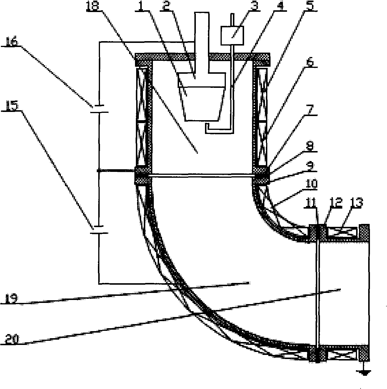
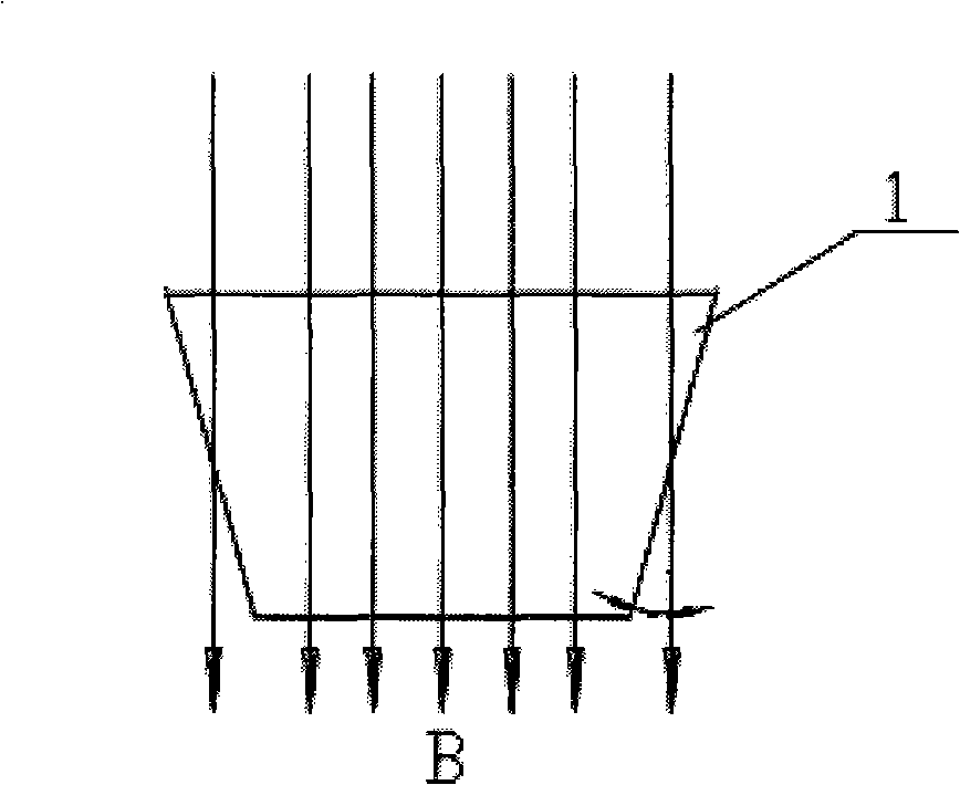
[0021] Such as Figure 1 to Figure 2 As shown, the water-cooled anode cylinder 7 is provided with a truncated-conical cathode 1 installed on the cathode water-cooled seat 2, a trigger pin 4 connected with the trigger wire package 3, and stable wires are respectively wound up and down on the outside of the water-cooled anode cylinder 7. The arc coil 5 and the focusing coil 6, the deflection coil 10 is wound outside the water-cooled filter elbow 9, the lead-out coil 13 is wound outside the water-cooled lead-out straight pipe 12, and the arc discharge is connected between the water-cooled anode cylinder 7 and the cathode water-cooled seat 2 A power supply 16, a positive bias power supply 15 is connected between the water-cooled filter elbow 9 and the water-cooled anode cylinder 7

specific Embodiment approach 2

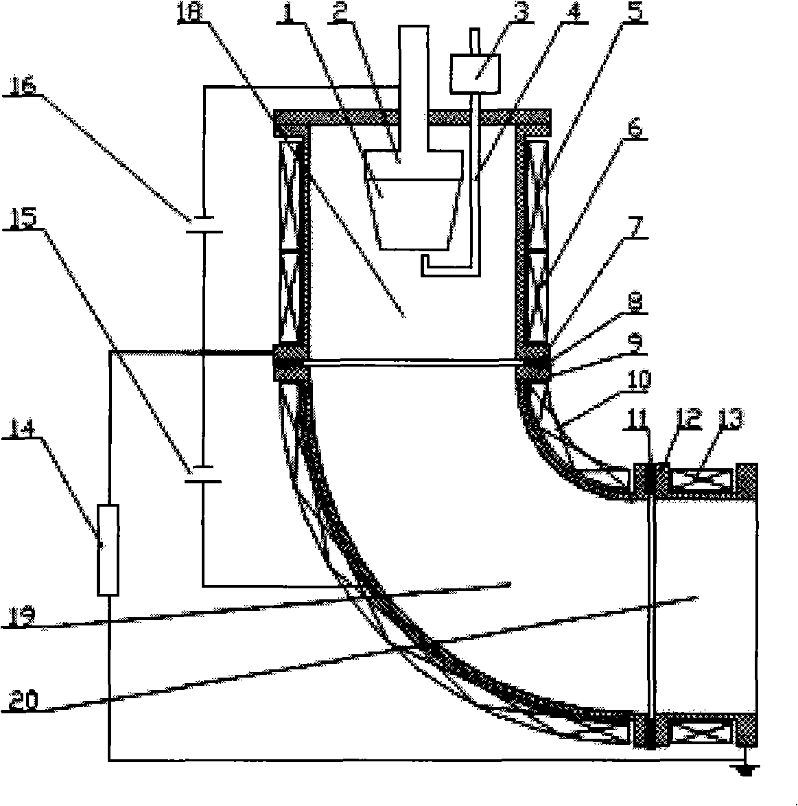
[0022] Such as image 3 As shown, on the basis of Embodiment 1, a resistor 14 is connected between the water-cooled anode cylinder 7 and the water-cooled straight pipe 12,

specific Embodiment approach 3

[0023] Such as Figure 4 As shown, on the basis of Embodiment 1, an air supply pipe 17 is added at the top of the water-cooled anode cylinder 7, and Ar, N 2 、C 2 h 2 Wait for the working gas to be sent into the plasma generation area 18, so that the working gas also participates in the plasma discharge,


PUM


Abstract

The invention belongs to a plasma source, particularly claims a DC magnetic filtered cathode vacuum arc plasma source. The plasma source is characterized in that a positive bias power supply reduces the loss of the plasma effectively, improves the output efficiency, restrains and stabilizes cathode arc discharging in the cathode head face by using the included angle of the axial magnetic field and the conical cathode inclined plane, so that the invention can work under high vacuum, and the evenness of the plasma entering the vacuum cavity is improved; a resistor can be connected between the water cooling anode cylinder and the water cooling leading-out straight tube, the low plasma output efficiency and the over heat phenomenon of the water cooling leading-out straight tube due to direct grounding of the anode are avoided, thus further improving the output efficiency of the plasma; an air tube can be applied to inflating working gas in the plasma generating area, to participate in plasma discharging, such a method is helpful for depositing high-quality reaction membrane on the work pieces.

Description

technical field [0001] The invention belongs to a metal plasma source, in particular to a plasma source for material surface treatment. Background technique [0002] The deposition of decorative or functional films on metal or non-metal surfaces has developed rapidly in recent years, and people's requirements for decorative and functional films are increasing day by day. Vacuum cathode arc discharge, as a main means of metal plasma generation, is widely used in functional and decorative coatings. However, the generation of metal plasma by vacuum cathode arc discharge is accompanied by the generation of liquid droplets or large particles. The metal plasma generated by conventional small multi-arc target discharge directly faces the workpiece to be processed, resulting in liquid droplets or large particles. It is deposited on the surface of the workpiece, thereby reducing the compactness of the film, the bonding force of the film base, and the brightness of the film. Therefo...

Claims


Application Information

Patent Timeline
IPC IPC(8): H05H1/34H05H1/40H01J37/08C23C16/513
Inventor 唐德礼童洪辉蒲世豪谢峰
Owner SOUTHWESTERN INST OF PHYSICS
Learn More