
Device and method for measuring cornea curvature

A technology of cornea and curvature, which is applied in the field of measuring corneal curvature, can solve the problems of increased product cost, longer measurement time, increased measurement calculation error and mechanical failure, and achieves the effect of saving manufacturing cost and maintenance cost, and the method and device are simple

Active Publication Date: 2010-06-16
株式会社湖碧驰 +1
View PDF0 Cites 14 Cited by
  • Summary
  • Abstract
  • Description
  • Claims
  • Application Information

AI Technical Summary

Problems solved by technology

[0009] This makes conventional devices have the disadvantage that the total measurement time becomes longer, and if the position of the eye to be measured changes when the aperture 14 is inserted, erroneous corneal curvature values ​​may be obtained
Moreover, it is also difficult for eye measurers to perceive the position changes of the measured eyes during the measurement process.
Conventional devices also have a disadvantage: conventional devices require an aperture 14, a precision motor 10 to drive the aperture 14, and a control circuit to drive them
This makes the product cost increase and the mechanical structure more complicated
At the same time, this also increases the probability of measurement calculation errors and mechanical failures, which in turn are caused by changes in the telecentric area of ​​​​the measurement light caused by the deviation of the aperture during use or the performance of the aperture motor.

Method used


Image

  • Device and method for measuring cornea curvature
  • Device and method for measuring cornea curvature
  • Device and method for measuring cornea curvature

Examples


Embodiment Construction

[0025] A more complete understanding of the present invention and its attendant advantages will be obtained by reference to the following detailed description taken in conjunction with the accompanying drawings.

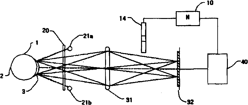
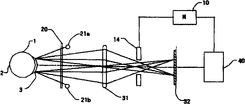
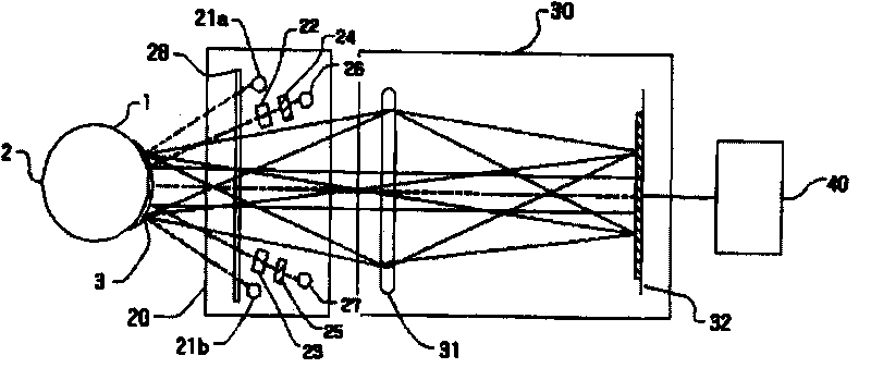
[0026] image 3 is a diagram illustrating a corneal curvature measuring device according to an embodiment of the present invention. Figure 4 is a diagram illustrating a situation where micro-inverted ring light and focused light are incident on the cornea in a keratometry device according to an embodiment of the present invention.

[0027] Such as image 3 Said, according to one embodiment of the present invention, the corneal curvature measuring device includes a micro-inverted ring optical system 20, an imaging optical system 30, and a computing and control unit 40, and also includes a light transmission device for reflecting the measured eye 1 back The measurement light is transmitted to the mirror and relay lens of the imaging optical system 30.

[0028] The ...


PUM


Abstract

The present invention provides a device and a method for measuring cornea curvature by using microreciprocal degree ring lights and focused lights for automatically eliminating measurement error caused by position change of an eye to be measured. The device for measuring cornea curvature comprises a microreciprocal degree ring light source for emitting ring lights to the cornea of an eye to be measured, a focused light source for emitting two spot type focused lights to the cornea of the eye to be measured, an image optics system for detecting an microreciprocal degree ring light image and focused light images that are reflected from the cornea, and an operation and control unit for obtaining the diameter R of the microreciprocal degree ring light image at a measurement mode and distance F between spots of the focused light images at the measurement mode from the microreciprocal degree ring light image and the focused light images detected by the image optics system, for compensating the diametric error of the microreciprocal degree ring light image as a consequence of position change of the eye, and calculating the cornea curvature of the eye to be measured according to the compensated microreciprocal degree ring light image.

Description

[0001] This application claims priority from Korean Patent Application No. 10-2008-0117273 filed on November 25, 2008. The entire disclosure of this Korean patent application is incorporated herein by reference. technical field [0002] The present invention relates to a method and apparatus for measuring the curvature of the cornea, and more particularly to such a method and apparatus for measuring the curvature of the cornea in which the Measurement error caused by changes in eye position. Background technique [0003] Various ophthalmic instruments are used to diagnose eye conditions, such as refractometers for objectively measuring the refractive power of the eye, devices for measuring the shape / curvature of the cornea (often called an opthalmometer), and The contact method measures intraocular pressure with a tonometer and the like. In particular, the keratometry device, as an optoelectronic measurement system, is composed of optical components, electronic components ...

Claims


Application Information

Patent Timeline
IPC IPC(8): A61B3/107
CPCA61B3/107G01B11/24G01M11/025G01N2021/0181
Inventor 金炯旭
Owner 株式会社湖碧驰
Learn More