
Continuous extrusion method and equipment for producing large-width copper strip base from noncircular rod material

A technology of extrusion equipment and extrusion method, which is applied in the direction of metal extrusion, metal processing equipment, metal extrusion dies, etc., can solve the problems of inability to extrude width-thickness ratio, etc., achieve easy operation, improve processing efficiency, and reduce production costs Effect

Inactive Publication Date: 2010-06-16
大连康丰科技有限公司
View PDF4 Cites 12 Cited by
  • Summary
  • Abstract
  • Description
  • Claims
  • Application Information

AI Technical Summary

Problems solved by technology

[0005] The purpose of the present invention is to provide a continuous extrusion method using non-circular billets in order to overcome the shortcomings of existing continuous extrusion methods that cannot extrude products with a large aspect ratio. , continuous extrusion to produce copper strip products with a width-thickness ratio greater than 20; another object of the present invention is to provide a continuous extrusion equipment using non-circular billets, with special extrusion wheel grooves corresponding to non-circular billets Grooves, cavity inlets and dies for continuous extrusion machines to produce flat copper strip

Method used


Image

  • Continuous extrusion method and equipment for producing large-width copper strip base from noncircular rod material
  • Continuous extrusion method and equipment for producing large-width copper strip base from noncircular rod material
  • Continuous extrusion method and equipment for producing large-width copper strip base from noncircular rod material

Examples


Embodiment Construction

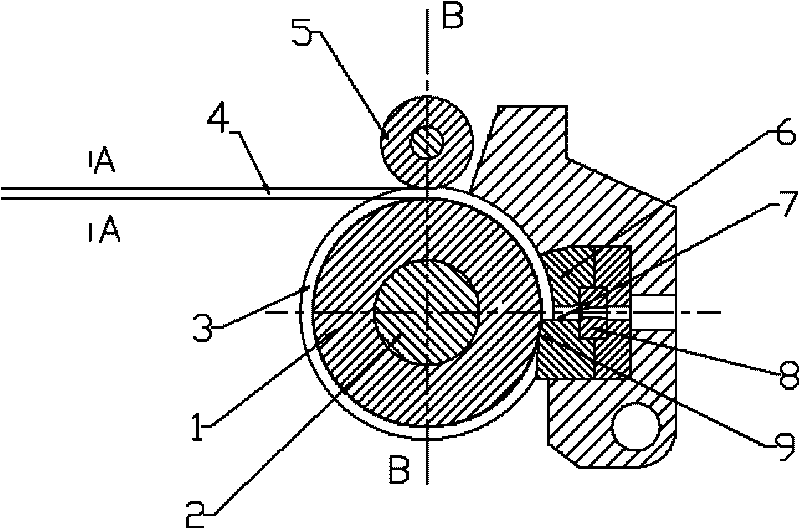
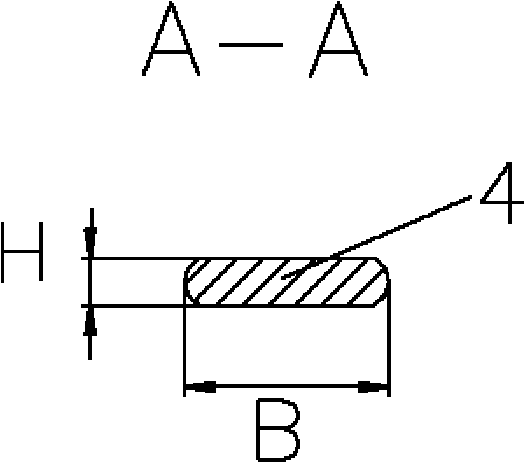
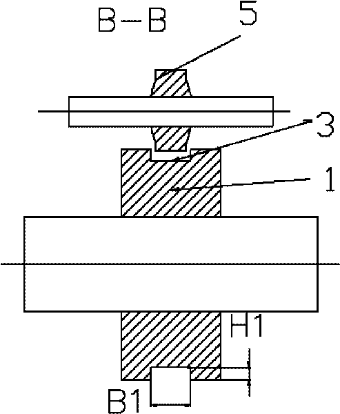
[0022] Such as Figure 1-7 The shown continuous extrusion equipment adopts a non-circular billet, the rotary extrusion wheel 1 is installed on the rotating shaft 2, and the rotary extrusion wheel 1 has an annular groove 3 in the circumferential direction, and the entrance width of the groove 3 is larger than or equal to the width of the non-circular blank, at image 3 Among them, the groove width B1 of the extrusion wheel is the width B of the slab plus (0-10mm), that is, B1=B+(0-10mm), and the depth H1 of the groove of the extrusion wheel is the thickness H of the slab plus (0 -5mm), that is, H1=H+(0-5mm).

[0023] The cross-sectional shape of the block on the cavity 6 depends on the cross-sectional shape and size of the extrusion wheel groove 3. Figure 4-6 Among them, the cross-sectional shape of the material blocking block 9 of the cavity is a non-circular section with rounded corners, and the width B2 of the material blocking block 9 is the extrusion wheel groove width ...


PUM


Abstract

The invention relates to the technical field of continuous extrusion. A noncircular blank continuous extrusion method is adopted, the noncircular blanks enter the groove of a rotary extrusion wheel through a compaction wheel, and are driven by the friction of the groove of a rotary extrusion wheel through a compaction wheel to reach the end surface of a baffle block of a cavity body and enter the cavity body from a cavity body material inlet, and finally are extruded into finished products by a mould. The invention adopts the noncircular blanks to be extruded continuously, thereby effectively solving the technical problem that products with the flakiness ratio above 20 can not be extruded continuously. The invention has simple production process and easy operation is easy and can improve processing efficiency and reduce production cost. The invention also discloses continuous extrusion equipment with simple structure. On the basis of using traditional standard structures and components as much as possible, the invention improves part of structures of the rotary extrusion wheel and the cavity body to match the noncircular blank continuous extrusion, thereby reducing the load of the extrusion wheel and the cavity body during extruding and successfully extruding out a cooper strip product with the flakiness ratio above 20.

Description

[0001] Field: [0002] The invention relates to the field of metal plastic forming, especially a metal continuous extrusion method; in addition, the invention also relates to continuous extrusion equipment. Background technique: [0003] The blanks used in traditional continuous extrusion are round rods, which are used to extrude non-ferrous metals. When extruding difficult-to-extrude products, especially copper alloy products, the ratio of the width to thickness of the extruded product is limited. Domestic invention patent 200610047956.2 provides a continuous extrusion method of extended extrusion, which starts to expand the billet at the feed port of the extrusion cavity to achieve the purpose of extruding products with larger specifications. The world patents WO2004076087A1 and WO0232595 of the British BWE company provide continuous extrusion equipment and methods for copper materials, and the blank used is a round rod. Domestic patents 200710071577.1, 200710000936.4, and ...

Claims


Application Information

Patent Timeline
IPC IPC(8): B21C23/02B21C23/21B21C26/00B21C25/02
Inventor 宋宝韫刘元文
Owner 大连康丰科技有限公司
Learn More