

Working handpiece of numerical control wire bending machine
A technology of wire bending machine and head, which is applied in the field of wire bending machine manufacturing, can solve the problems of increased head load, low wire processing efficiency, heavy head load, etc., and achieves high positioning angle accuracy and high wire forming efficiency , the effect of light load of its own weight
- Summary
- Abstract
- Description
- Claims
- Application Information
AI Technical Summary
Problems solved by technology
Method used
Image

Examples
Embodiment 1
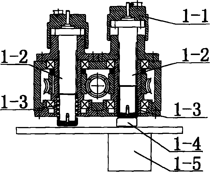
[0018] Embodiment 1: with reference to attached Figure 1-8 . The working head of the CNC wire bending machine, which includes the working head of the CNC wire bending machine, the two die heads 1-1 in the wire bending machine die change and steering die lifting avoidance mechanism in the CNC wire bending machine are respectively connected to the The two spline shafts 1-2 are connected without relative displacement, the bottom of the spline shaft 1-2 is in contact with the lower end of the compression spring 1-3, and the upper end of the compression spring 1-3 is in contact with the inner step of the main shaft and drives the spline shaft 1-2 move down. When the die head 1-1 that needs to work is turned to the center of the station, the piston head 1-4 in the oil cylinder or cylinder 1-5 lifts up the spline shaft and the die head 1-1 together, and the compression spring 1-3 is compressed again; When it is necessary to change the mold or turn the die head 1-1, the piston head...
PUM
 Abstract
Description
Claims
Application Information