Vacuum clamp for machining porous sheet and using method thereof

A technology of vacuum clamping and thin plate, which is applied in the direction of manufacturing tools, workpiece clamping devices, metal processing equipment, etc., can solve the problems of difficult and thin plate workpiece machining accuracy, inability to achieve positioning, etc., and achieves high machining accuracy, good implementation effect and cost. low effect

Inactive Publication Date: 2010-06-16
SUZHOU CHUNXING PRECISION MECHANICAL
View PDF0 Cites 24 Cited by
  • Summary
  • Abstract
  • Description
  • Claims
  • Application Information

AI Technical Summary

Problems solved by technology

This kind of vacuum fixture adopts unitized vacuum chucks. However, the shapes and structures of the workpieces in the metal machining industry are different. The general-purpose unitized vacuum chucks cannot match the shape and structure of the workpieces, and cannot achieve accurate positioning. Guarantee the processing accuracy of thin plate workpieces

Method used


Image

  • Vacuum clamp for machining porous sheet and using method thereof
  • Vacuum clamp for machining porous sheet and using method thereof
  • Vacuum clamp for machining porous sheet and using method thereof

Examples


Embodiment Construction

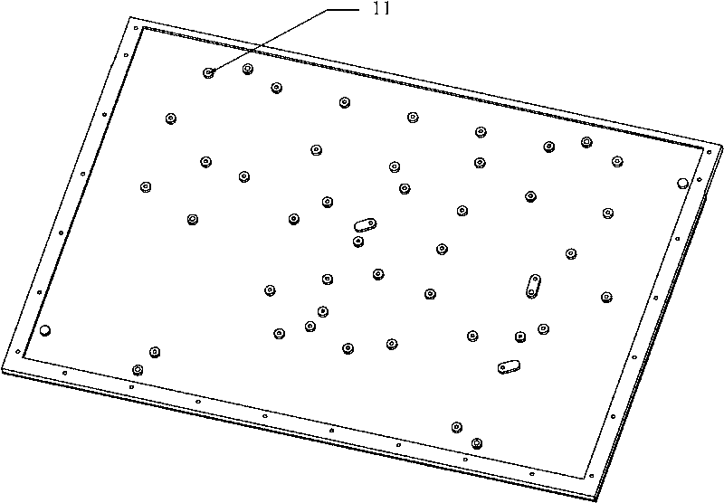
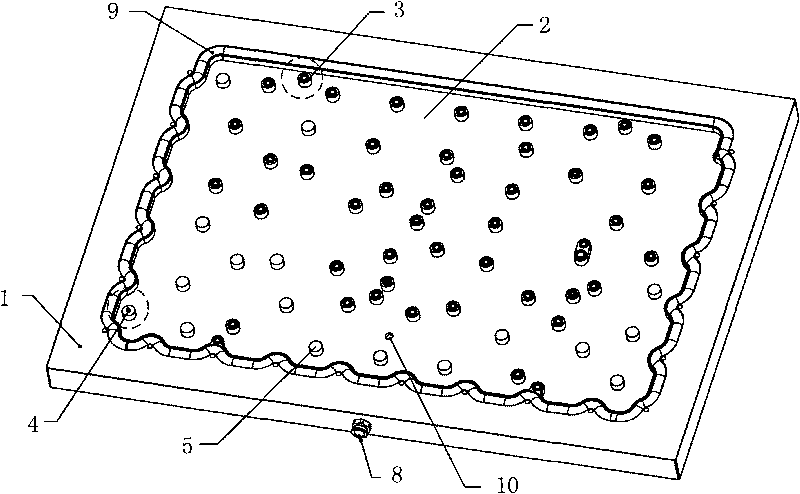
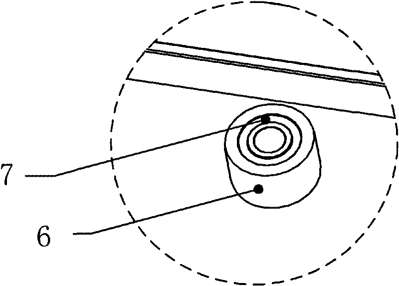
[0028] Such as Figure 1~5 The shown vacuum fixture for porous thin plate processing involves parts to be processed, including a substrate 1, a positioning device, an air guiding device, a vacuum generating device and a sealing device, and its special feature is that: the substrate 1 is distributed with A shallow cavity 2 adapted to the shape of the workpiece to be processed, and air guide holes 10 are distributed in the shallow cavity 2 . Thus, during the processing, the shallow cavity 2 can form a vacuum cavity with the bottom surface of the processed part, and the processed part can be adsorbed on the substrate 1 . At the same time, the positioning device restricts the movement of the processed part on the base plate 1, so that the processed part is in a reliable clamping state for machining. The air guiding device connects the substrate 1 and the vacuum generating device. The sealing device includes a sealing strip 9 and a through-hole sealing element 3. The sealing strip...


PUM


Abstract

The invention relates to a vacuum clamp for machining a porous sheet and a using method thereof and belongs to the technical field of conveying thin appliances. The vacuum clamp comprises a baseplate, a positioning device, an air guide device, a vacuum generating device and a sealing device; the vacuum clamp is characterized in that: shallow cavities adaptive to the shape of a machined part are distributed on the baseplate; air guide holes are distributed in each shallow cavity; each shallow cavity and the underside of the machined part form a vacuum cavity, so the machined part is adsorbed on the baseplate; the positioning device limits the movement of the machined part on the baseplate so as to make the machined part in a clamping state; the air guide device is connected with the baseplate and the vacuum generating device; the sealing device comprises sealing bars and through hole sealing elements; the sealing bars are distributed on the peripheral edges of the shallow cavities; and the through hole sealing elements are distributed in the shallow cavities. The vacuum clamp adopts a reliable positioning mode, the shape of the vacuum cavities is matched with the shape of the part, and the adsorption area can be farthest utilized.

Description

technical field [0001] The invention relates to a clamp and its use method, in particular to a vacuum clamp for processing a porous thin plate and its use method, and belongs to the technical field of thin handling equipment. Background technique [0002] In the existing mechanical processing industry, many workpieces belong to the thin plate category. Because the workpiece is thin, if the traditional fixture clamped on the side is used, the workpiece is easily deformed and cannot meet the processing accuracy; if the clamp clamped on the top surface is used, the upper surface Unable to process, only multi-process processing can be adopted, resulting in low efficiency. Furthermore, multiple times of clamping will make it impossible to guarantee the accuracy of each machining level of the workpiece, which is not conducive to popularization. In order to solve the problems existing in the above-mentioned conventional fixtures, a vacuum fixture that utilizes vacuum suction force...

Claims


Application Information

Patent Timeline
Patent Type & Authority Applications(China)
IPC IPC(8): B23Q3/00B25B11/00
Inventor 王书强
Owner SUZHOU CHUNXING PRECISION MECHANICAL
Why Eureka
Try Eureka