Pneumatic tire

A technology for pneumatic tires, tire width direction, applied in tire parts, tire tread/tread pattern, transportation and packaging, etc. The effect of improving braking performance

Active Publication Date: 2010-06-16
TOYO TIRE & RUBBER CO LTD
View PDF8 Cites 22 Cited by
  • Summary
  • Abstract
  • Description
  • Claims
  • Application Information

AI Technical Summary

Problems solved by technology

However, this tire structure is mainly designed to improve the stability of snow handling, and there is no suggestion of any solution to the problem of securing the ground contact area on the inside of the vehicle and further improving the cornering performance when the car is turning.

Method used


Image

  • Pneumatic tire
  • Pneumatic tire
  • Pneumatic tire

Examples


Embodiment Construction

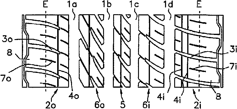
[0039] Embodiments of the present invention will be described with reference to the drawings. figure 1 A developed view showing an example of a tread of a pneumatic tire according to the present invention. This tire is a mounting-direction-specific tire having a left-right asymmetrical tread pattern, and when mounted on a vehicle, the right side in the drawing corresponds to the vehicle inner side, and the left side in the drawing corresponds to the vehicle outer side. Symbol E is the ground terminal.

[0040] This tread is provided with four main grooves 1a to 1d extending in the circumferential direction and five block rows defined by these main grooves. On the outside of the outermost main grooves 1a, 1d in the tire width direction, shoulder ground contact portions 2o, 2i are formed, and the block rows constituting these shoulder ground contact portions are composed of a plurality of patterns partitioned by lateral grooves 3o, 3i. Block 8 constitutes. In addition, in the...


PUM


Abstract

A pneumatic tire has a tread pattern including a plurality of main grooves extending along a tire circumferential direction, and a shoulder land portion constructed by a rib or a block row formed in an outer side in a tire width direction of the main groove positioned in an outermost side. A circumferential sipe is provided in each of the shoulder land portions in both sides in the tire width direction. The number of the circumferential sipes provided in the shoulder land portion in a vehicle inner side is larger than the number of the circumferential sipes provided in the shoulder land portion in a vehicle outer side.

Description

technical field [0001] The present invention relates to a pneumatic tire having a tread pattern including a plurality of main grooves extending in the tire circumferential direction and shoulder ground contact portions formed of longitudinal patterns or blocks. Background technique [0002] Various tread patterns that meet the required tire performance and service conditions are formed on the tread of the pneumatic tire. On the ground contact portion of the tread, grooves called sipe are sometimes formed, and since the edge effect of the sipe grips the road surface, it is not only on icy and snowy roads but also on wet or dry roads. , It can also improve the turning performance of the car when turning or the braking performance when braking. [0003] Patent Document 1 below describes a pneumatic tire in which circumferential sipes are provided on blocks and the circumferential sipe formation density is higher on the vehicle outer side than on the vehicle inner side. This i...

Claims


Application Information

Patent Timeline
Patent Type & Authority Applications(China)
IPC IPC(8): B60C11/117B60C11/03
CPCB60C11/1218B60C2011/1295B60C2011/1209B60C11/0332B60C11/0306B60C11/12B60C11/1263
Inventor 宫崎哲二
Owner TOYO TIRE & RUBBER CO LTD
Why Eureka
Try Eureka