Method for controlling well depth positioning in deposit drilling

A control method and a technology for positioning wells, which are applied to the automatic control system of drilling, drilling equipment, earthwork drilling and production, etc., to achieve the effect of improving measurement accuracy

Inactive Publication Date: 2010-06-16
DANDONG DONGFANG MEASUREMENT&CONTROL TECHCO
View PDF4 Cites 19 Cited by
  • Summary
  • Abstract
  • Description
  • Claims
  • Application Information

AI Technical Summary

Problems solved by technology

[0005] Aiming at the problems existing in the existing drilling operation, the present invention proposes a measurement control method with accurate drilling positioning and accurate hole depth measurement

Method used


Image

  • Method for controlling well depth positioning in deposit drilling
  • Method for controlling well depth positioning in deposit drilling
  • Method for controlling well depth positioning in deposit drilling

Examples


Embodiment approach

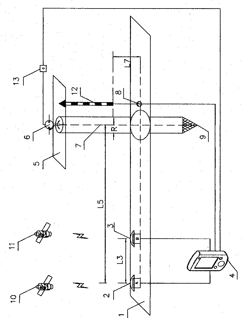
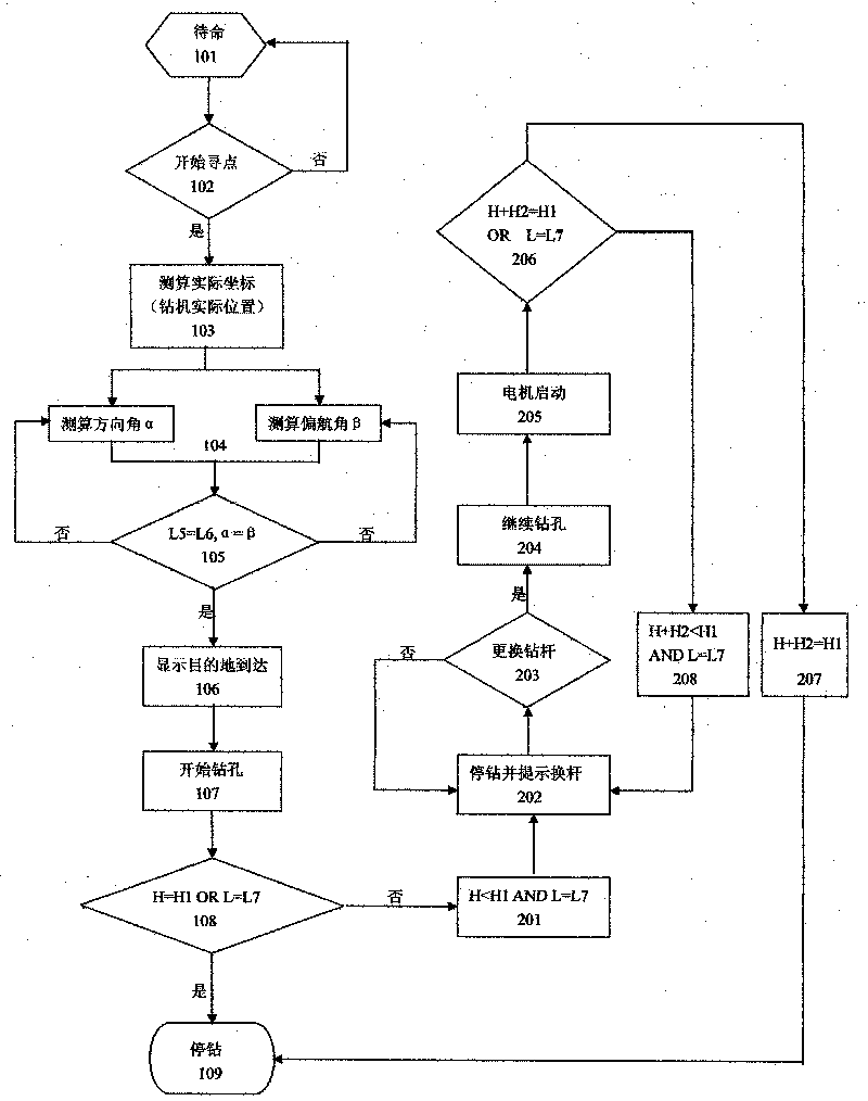
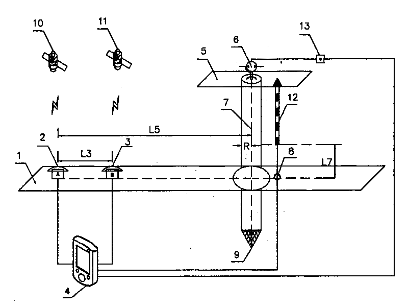
[0015] Step 101 is a standby program. When the measuring device is started, it enters the step 102 of starting to find a point. The positions of the two GPS antennas 2 and 3 are respectively A point and B point, the distance from A point to B point and the distance from A point to the drill pipe. The distance of 7 can be measured by laser rangefinder 8, which are constants L3 and L4 respectively, and the radius of the drill rod is R, then the distance from point A to the center of drill rod 7 is constant L5=L4+R. The GPS module measures the current location coordinates (longitude, latitude, elevation) of the drilling rig and stores them in the vehicle-mounted terminal device. The coordinates are WGS84 longitude and latitude coordinates, which are converted into Beijing May 4th coordinates (X1, Y1, Z1) through the parameter conversion of the vehicle-mounted terminal device 4, which is the step 103 of the actual position of the drilling rig. The coordinate map of the drilling po...


PUM


Abstract

The invention relates to a method for controlling well depth positioning in deposit drilling, which enable a drilling machine to accurately find a position to be drilled by employing GPS (Global Position System) positioning and a laser ranging method and completes drilling operation according to the detection data of a laser range finder during drilling. Adopting the laser ranging, the method avoids counting error of a single chip microcomputer, resulting from rock stratums with different hardness and severe vibration of the drilling machine when the photoelectric counting mode of the traditional method is used to measure drilling depth, thereby improving the measurement precision of drilling depth.

Description

technical field [0001] The invention relates to a method for drilling positioning and well depth control of ore deposits, in particular to a control method for high-precision GPS positioning and laser distance measurement for hole depth measurement in drilling operations. Background technique [0002] At present, drilling operations mainly rely on manual methods. Before drilling operations, professional geologists will carry heavy equipment to the site to measure and plan according to the requirements of the area to be operated, such as the scope of operation, grade, and storage capacity, and determine the backswing of the points to be drilled. Put stones or pile up lime powder as a sign of the operating point. After the drilling rig arrives at the operation area, the drilling rig driver moves the equipment while visually observing the target point. Under the influence of natural factors and human factors, the drilling positioning is inaccurate and wastes a lot of manpower a...

Claims


Application Information

Patent Timeline
Patent Type & Authority Applications(China)
IPC IPC(8): E21B44/00E21B47/02E21B47/04E21B47/022
Inventor 郑学明石国峰高德旭吴耀昕樵永锋杨兴海加子东
Owner DANDONG DONGFANG MEASUREMENT&CONTROL TECHCO
Why Eureka
Try Eureka