
Wave spring holding structure and frictional engagement apparatus

A friction engagement device, wave spring technology, applied in the direction of spring, spring/shock absorber, cup spring, etc., can solve problems such as damage to wave spring function

Inactive Publication Date: 2010-06-16
TOYOTA JIDOSHA KK
View PDF4 Cites 15 Cited by
  • Summary
  • Abstract
  • Description
  • Claims
  • Application Information

AI Technical Summary

Problems solved by technology

In this case, when the wave spring turns relative to the snap ring, the end of the wave spring enters the gap formed in the snap ring, impairing the function of the wave spring.

Method used


Image

  • Wave spring holding structure and frictional engagement apparatus
  • Wave spring holding structure and frictional engagement apparatus
  • Wave spring holding structure and frictional engagement apparatus

Examples


Embodiment Construction

[0023] Hereinafter, embodiments of the present invention will be described with reference to the drawings. In the drawings, the same or corresponding parts are denoted by the same reference numerals, and their descriptions will not be repeated.

[0024] In the following embodiments, each constituent element is not necessarily essential to the present invention unless specified. In addition, in the following embodiments, if the number, quantity, etc. of units are mentioned, the number of units, etc. are exemplary, and the present invention is not necessarily limited to the number, quantity, etc. of units unless specified.

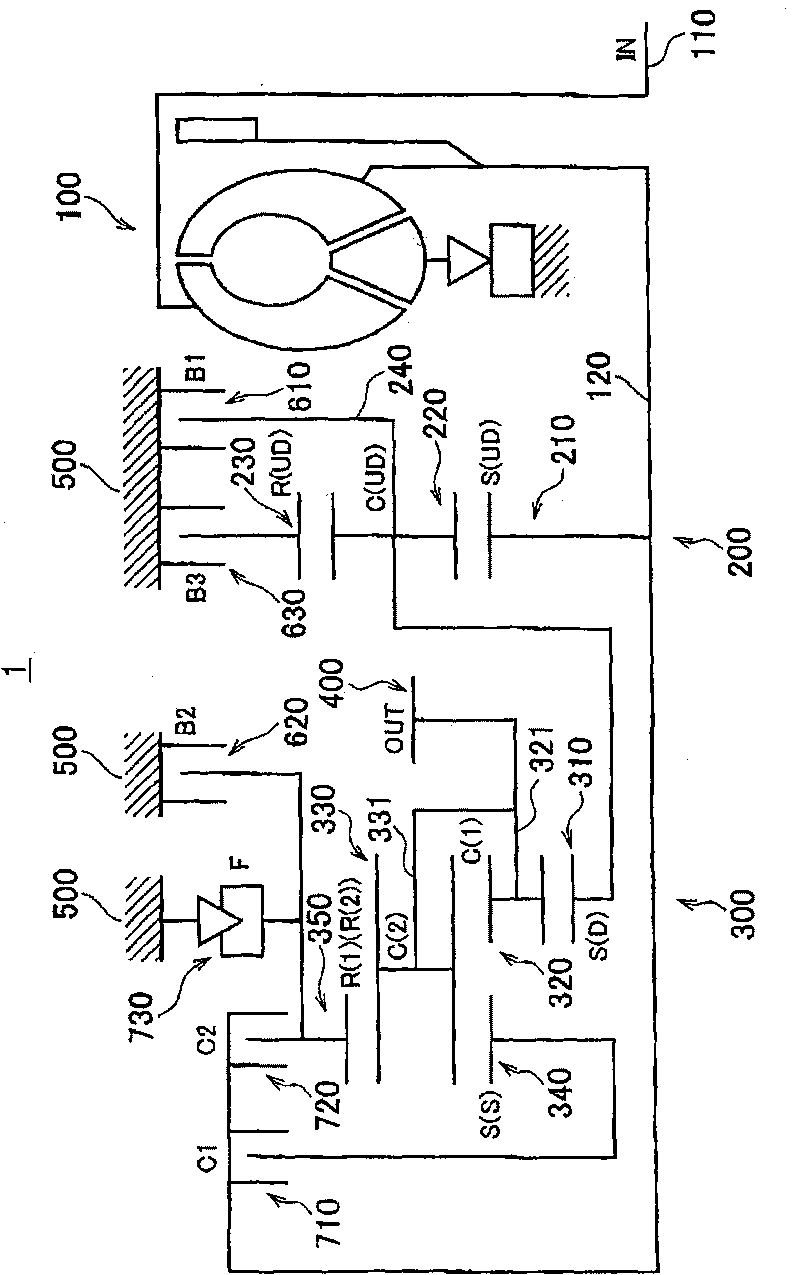
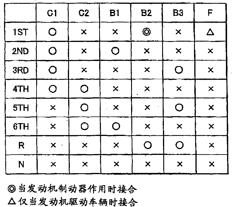
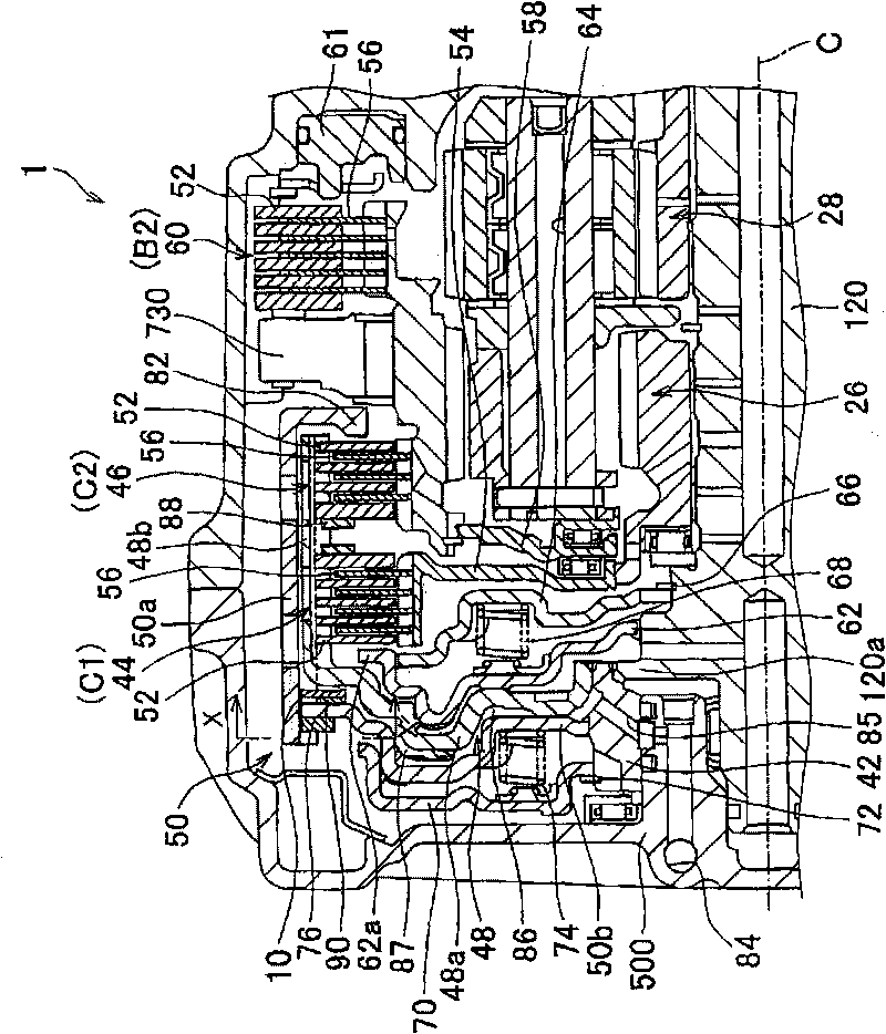
[0025] figure 1 is a schematic diagram showing the configuration of an automatic transmission employing a frictional engagement device according to an embodiment of the present invention. This embodiment shows an example in which the automatic transmission 1 as the power transmission device is an automatic transmission provided on a vehicle. Such as figu...


PUM


Abstract

The invention relates to a wave spring holding structure and a frictional engagement apparatus. The wave spring holding structure includes a wave spring (90) that includes crest portions (91) and recessed portions (92) that are alternately formed in a circumferential direction thereof, and a first gap (93); a circular member (50b) provided to be rotatable around an axis; and an arc-shaped snap ring (10) that includes a second gap (12), and that restricts movement of the circular member (50b) in a direction of the axis. The wave spring (90) and the snap ring (10) share the axis with the circular member (50b). The wave spring (90) and the snap ring (10) are rotatable with respect to each other. The wave spring (90) is disposed and held between the circular member (50b) and the snap ring (10) so that the crest portions (91) protrude toward the circular member (50b), and the recessed portions (92) protrude toward the snap ring (10). The first gap (93) is formed in one of the crest portions (91).

Description

technical field [0001] The present invention relates to a wave spring retaining structure and a friction engagement device. Background technique [0002] In a friction engagement device used in an automatic transmission for a vehicle or the like, an annular disk spring is provided between a multi-disc clutch and a piston controlling engagement of the multi-disc clutch to absorb shock when the clutch is engaged. For example, Japanese Patent Application Laid-Open Document No. 2005-282807 (JP-A-2005-282807) and Japanese Patent Application Laid-Open Document No. 9-303455 (JP-A-9-303445) describe the conventional disc springs. technology. [0003] Conventional disc springs are complete rings without any cut-offs along the circumference. Conventional disc springs are produced by stamping using a press or the like. Therefore, the utilization rate of the material is low, and the cost increases. Thus, a C-shaped spring (so-called wave spring) has been proposed which is formed by ...

Claims


Application Information

Patent Timeline
Patent Type & Authority Applications(China)
IPC IPC(8): F16F1/32F16D25/0638
CPCF16D25/0638F16F1/328F16D25/10F16D2048/0212F16B2200/71
Inventor 后藤慎太郎原岛照加藤直纪
Owner TOYOTA JIDOSHA KK
Learn More