
Vacuum valve

A technology of vacuum valve and valve core, which is applied in the direction of lifting valve, valve details, valve device, etc., and can solve the problem of complex decomposition operation process and so on

Active Publication Date: 2010-06-16
CKD
View PDF1 Cites 6 Cited by
  • Summary
  • Abstract
  • Description
  • Claims
  • Application Information

AI Technical Summary

Problems solved by technology

In addition, when the vacuum valve 100 is disassembled, it is necessary to attach and detach the gap eliminating member 140, and the disassembly process is relatively complicated.

Method used


Image

  • Vacuum valve
  • Vacuum valve
  • Vacuum valve

Examples


no. 1 approach

[0046]

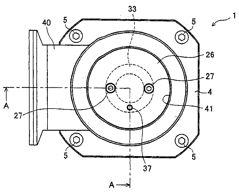
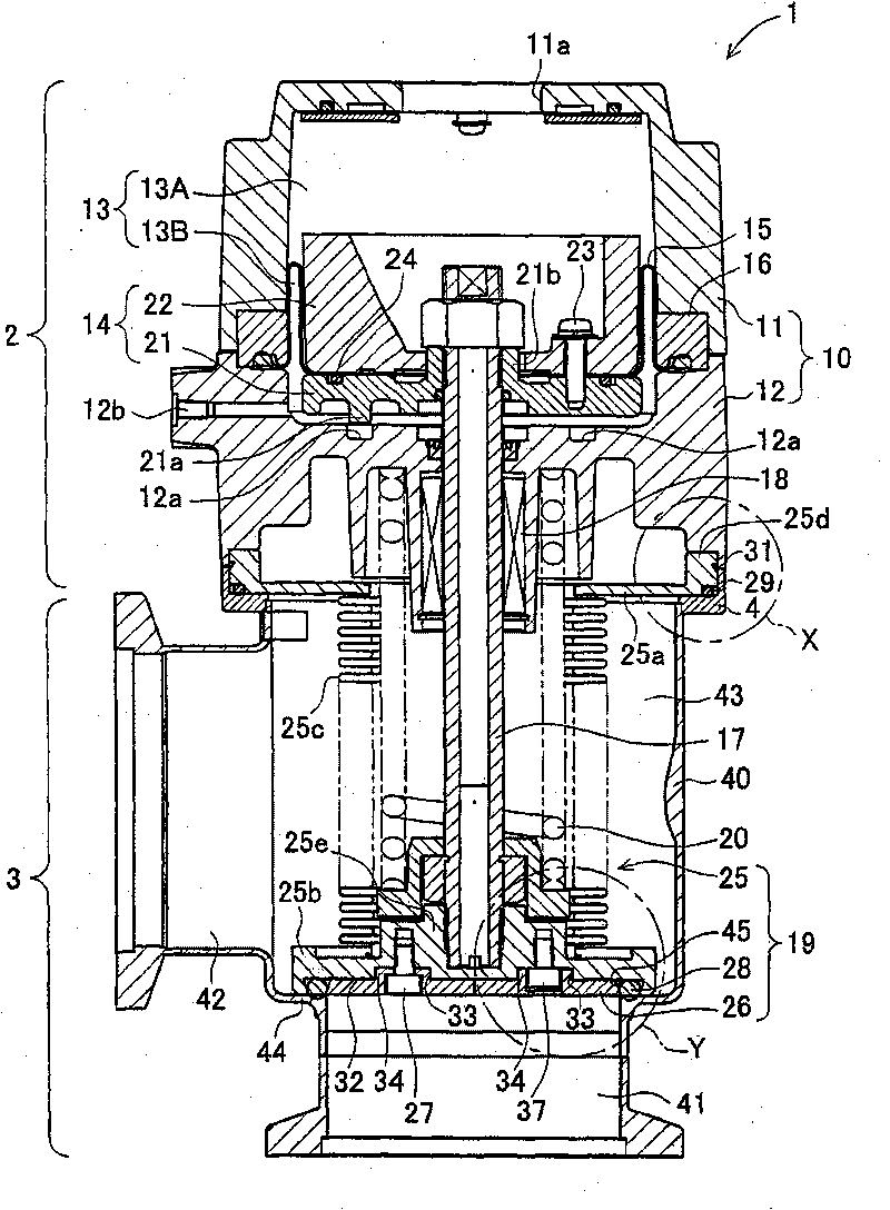
[0047] figure 1 is a bottom view of the vacuum valve 1. figure 2 yes figure 1 The AA profile.

[0048] The vacuum valve 1 has a drive unit 2 and a valve unit 3 . The driving part 2 and the valve part 3 are connected by four bolts 5 to form the appearance of the vacuum valve 1 .

[0049] Such as figure 2 As shown, the valve part 3 is arranged in the valve housing 40 . The first port 41 and the second port 42 of the valve housing 40 communicate via a valve chamber 43 . A valve seat 44 is formed on the inner surface of the valve chamber 43 . The valve body 19 is provided in the valve chamber 43 , and the valve body 19 can abut against the valve seat 44 or be separated from the valve seat 44 . In the valve chamber 43 of the valve housing 40, a bellows 25 as an example of a partition wall is arranged, and the bellows 25 is expandable and contractible according to the movement of the valve body 19. As shown in FIG. The connecting portion 4 is fixed to the outer ...

no. 2 approach

[0083] Next, a second embodiment of the present invention will be described with reference to the drawings. Figure 6 It is a cross-sectional view of a vacuum valve 1A according to a second embodiment of the present invention.

[0084] The vacuum valve 1A of the second embodiment is mainly different from the first embodiment in the connection structure of the drive unit 2 and the valve unit 3 . Therefore, here, the description will focus on points different from those of the first embodiment. In addition, about the same structure as 1st Embodiment, the same code|symbol as 1st Embodiment is attached|subjected in drawing, and description is abbreviate|omitted suitably.

[0085] The cylinder 10 is configured such that a closing member 62 and a cover 63 are attached to a cylindrical cylinder valve housing 61 , and a piston 68 is loaded to form a piston chamber 13B. The cylinder valve housing 61 is formed with an operation port 61a to communicate with the piston chamber 13B. The...


PUM


Abstract

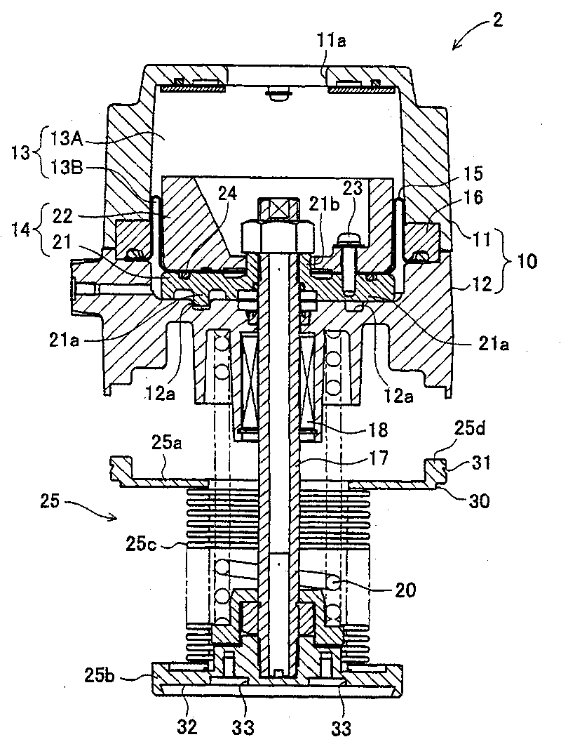
The present invention provides a vacuum valve having simple braking structure of a piston and easy disassembling operations. The vacuum valve (1) comprises a valve case (40) having a valve seat (44), a valve core (19) abutted against the valve seat (44) and separated from the valve seat, and a driving part (2) for exerting driving forces to the valve core (19). The driving part (2) comprises a driving shaft (17) connected with the valve core (19), a piston (14) connected at one side opposing to the valve core (19) of the driving shaft (17), an air cylinder (10) having a piston chamber (13) for containing the piston (14), and a waveshape dissepiment (15) held by the piston (14) and dividing the piston chamber (13), wherein, the piston (14) has a projection part (21a) projecting in the moving direction, and a braking part (12a) for braking the piston (14) by engaging with the projection part (21a) in a disassembling process is positioned on a surface opposing to the projection part (21a) on the air cylinder (10).

Description

technical field [0001] The invention relates to a vacuum valve arranged between a processing chamber and a vacuum pump for adjusting the vacuum pressure of the processing chamber. Background technique [0002] For example, in a CVD apparatus of a semiconductor manufacturing apparatus, a material gas including elements constituting a thin film material is supplied from the inlet of the reaction chamber to a sheet in a reaction chamber as a vacuum container, and a vacuum pump is used to exhaust gas from the outlet of the reaction chamber. Perform work to keep the reaction chamber in a vacuum state. The exhaust rate of the material gas is controlled by, for example, a butterfly proportional valve, but the butterfly proportional valve cannot completely shut off the piping. Therefore, an ON-OFF vacuum valve is arranged in series with the butterfly proportional valve to completely shut off the fluid in the piping. [0003] Figure 10 It is a sectional view of the vacuum valve 10...

Claims


Application Information

Patent Timeline
IPC IPC(8): F16K1/00F16K1/32F16K31/122F16K51/02
CPCC23C16/4412F16K51/02
Inventor 渡边雅之吉安一智
Owner CKD
Learn More