
Light-emitting diode module

A technology of light-emitting diodes and circuit boards, which is applied in the field of light-emitting diode modules, can solve problems such as poor contact between light-emitting diode light strips and flexible circuits, insufficient joint strength to resist, and limited joint area, so as to reduce the risk of poor contact or falling off The effect of chance

Active Publication Date: 2010-06-16
AU OPTRONICS CORP
View PDF0 Cites 6 Cited by
  • Summary
  • Abstract
  • Description
  • Claims
  • Application Information

AI Technical Summary

Problems solved by technology

[0004] In the prior art, pressure welding is used to achieve electrical connection between the LED strip and the flexible circuit. However, due to the limited joint area, the joint strength is not enough to resist the pull of external force. Therefore, the LED lamp It is difficult to effectively solve the problem of poor contact between the strip and the flexible circuit or the problem that the flexible circuit falls off from the LED light strip

Method used


Image

  • Light-emitting diode module
  • Light-emitting diode module
  • Light-emitting diode module

Examples


Embodiment Construction

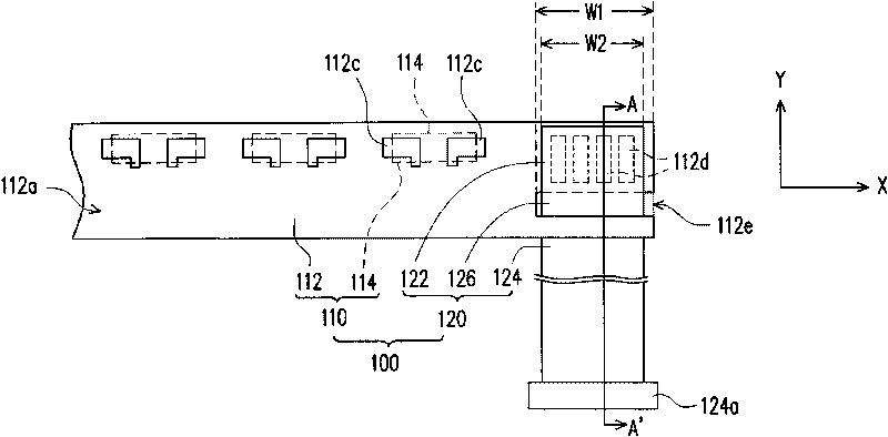
[0039] figure 1 is a schematic top view of a light emitting diode module according to an embodiment of the present invention, and Figure 2A as well as Figure 2B for along figure 1 The cross-sectional schematic diagram of the A-A' section line in the middle. Please refer to figure 1 and Figure 2A , the LED module 100 of this embodiment is suitable for electrical connection with a control circuit board (not shown), and the LED module 100 includes an LED light bar 110 and a flexible circuit 120 . The LED light bar 110 includes a circuit board 112 and a plurality of LED elements 114 . The circuit board 112 has a first surface 112a (or called an upper surface), a second surface 112b (or called a lower surface) opposite to the first surface 112a, a plurality of first contacts 112c, and a plurality of second contacts 112d and a slot 112e, and the first contact 112c and the second contact 112d are located on the first surface 112a. The LED element 114 is disposed on the firs...


PUM


Abstract

The invention discloses a light-emitting diode module which comprises a light-emitting diode lamp strip and a flexible circuit. The light-emitting diode lamp strip comprises a circuit board and a plurality of light-emitting diode elements. The circuit board comprises a first surface, a second surface, a plurality of first connecting points, a plurality of second connecting points and an open slot. The light-emitting diode elements are configured on the first surface and electrically connected with the first connecting points. The flexible circuit penetrates the open slot and is electrically connected with the second connecting points, and the flexible circuit comprises a first joint part, a second joint part and a bent part. The first joint part comprises a plurality of three connecting points which are electrically connected with the second connecting points, and the first joint part is in contact with the first surface of the circuit board. The second joint part comprises a plurality of fourth connecting points which are electrically connected with the control circuit board. The bent part is connected between the first joint part and the second joint part and penetrates the open slot.

Description

technical field [0001] The present invention relates to a light emitting element, and in particular to a light emitting diode module (LED module). Background technique [0002] Since liquid crystal displays (LCDs) have advantages such as low-voltage operation, no radiation scattering, light weight, and small size, which cannot be achieved by displays made by conventional cathode ray tubes (CRTs), LCDs have been used It has become the main topic of display research in recent years, and it is constantly developing towards colorization. [0003] Since the liquid crystal display is a non-self-illuminating display, a backlight unit is required to provide the required light to achieve the display function. In recent years, with the improvement of environmental awareness, the light-emitting elements used in the backlight have gradually changed from cold cathode fluorescent lamps (CCFL) to more environmentally friendly light-emitting diode elements. When the LED element is used in...

Claims


Application Information

Patent Timeline
Patent Type & Authority Applications(China)
IPC IPC(8): F21S8/00F21V23/00F21V23/06G02F1/13357F21Y101/02
Inventor 许子辉叶彦伯
Owner AU OPTRONICS CORP
Learn More