
Plasma melting cracking treating equipment

A pyrolysis treatment and plasma technology, applied in the field of ion melting pyrolysis treatment equipment, can solve problems such as failure to form current paths, failure to start arcs, and failure of equipment to work normally.

Active Publication Date: 2012-08-08
TAIZHOU WEIBO ENVIRONMENTAL PROTECTION EQUIP TECH
View PDF2 Cites 10 Cited by
  • Summary
  • Abstract
  • Description
  • Claims
  • Application Information

AI Technical Summary

Problems solved by technology

Since this furnace uses a single upper electrode, and the bottom electrode is the second electrode, once the power is turned off and the furnace is shut down during use, the processed material freezes and crystallizes on the bottom electrode to form a glass insulator, which will cause the upper electrode to No current path can be formed between the bottom electrode and the furnace, the arc cannot be started, and the equipment cannot work normally
In addition, Chinese patent: Ding Jialiang 200710023338.9 uses graphite rods as electrodes during use. Due to the consumption of graphite rods, the electrodes become shorter and shorter and need to be connected continuously. Continuous activity and wear, it is difficult to seal at high temperature, and toxic and harmful gases will overflow during work

Method used


Image

  • Plasma melting cracking treating equipment
  • Plasma melting cracking treating equipment
  • Plasma melting cracking treating equipment

Examples


Embodiment 1

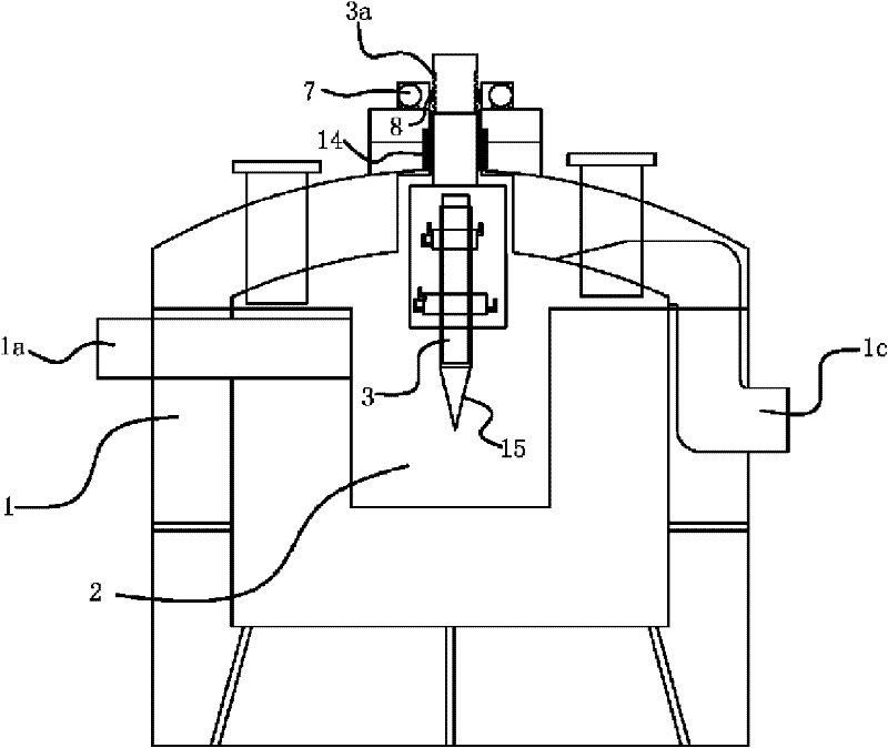
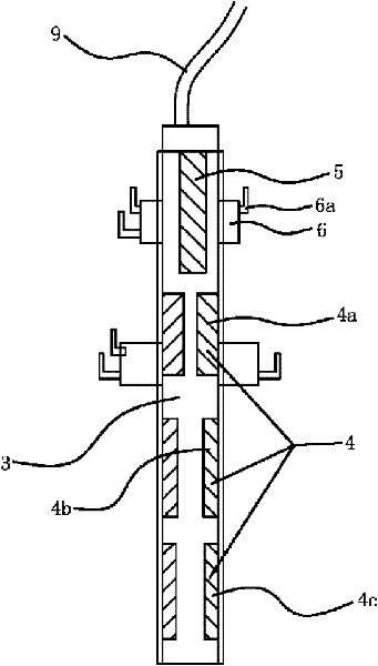
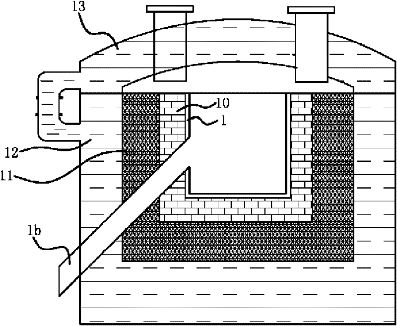
[0029] Such as figure 1 and figure 2 As shown, the plasma melting and cracking treatment equipment includes a body of furnace 1 having a feed port 1a and a discharge port 1b, and an incineration chamber 2 is provided in the body of furnace 1, and the incineration chamber 2 and the above-mentioned feed port 1a It communicates with the discharge port 1b, and a gas outlet 1c communicating with the incineration chamber 2 is also provided on the furnace body 1. A plasma torch generator capable of generating a plasma jet flame is also provided on the top of the furnace body 1, so One end of the plasma torch generator mentioned above penetrates in the combustion chamber 2, and the other end penetrates the body of furnace 1 and links to each other with a lifting mechanism that can drive it up and down.

[0030] The plasma torch generator comprises a torch rod 3, an anode 4, a cathode 5 and a gas transfer sleeve 6, the inside of the torch rod 3 has a cavity, and the anode 4 and the c...

Embodiment 2

[0038] The content in the second embodiment is roughly the same as that in the first embodiment, the difference is that the lifting mechanism in the first embodiment includes a motor 7 and a worm wheel 8, and the output shaft of the motor 7 is fixedly connected with the worm wheel 8 , the worm gear of the worm wheel 8 meshes with the above-mentioned tooth groove 3a; and the lifting mechanism in the second embodiment is a lifting cylinder, and the piston rod of the lifting cylinder is fixedly connected with the above-mentioned flare rod 3 . The work of cylinder, piston rod lifts up and down, thus drives the up and down of the torch rod 3 that is connected with it.


PUM


Abstract

The invention provides plasma melting cracking treating equipment belonging to the technical field of machines and solving the technical problems of low incineration temperature, poor incineration effect, insufficient incineration and the like of a traditional incineration furnace. The plasma melting cracking treating equipment comprises a furnace body with a charging port and a discharging port,wherein the furnace body is internally provided with an incineration cavity communicated with the charging port and the discharging port; the furnace body is also provided with a gas outlet communicated with the incineration cavity; the top of the furnace body is also provided with a plasma torch generator capable of generating plasma flames; one end of the plasma torch generator penetrates into the incineration cavity; and the other end penetrates out of the furnace body and is connected with a lifting mechanism capable of driving the plasma torch generator to lift upwards and downwards. Thetreating equipment has the advantages of higher flame temperature, more sufficient incineration, higher incineration efficiency and the like.

Description

technical field [0001] The invention belongs to the technical field of machinery, and relates to a plasma melting and cracking processing equipment, in particular to a plasma melting and cracking processing equipment for dangerous, poisonous and harmful articles. Background technique [0002] With the development of related industrial technology and the improvement of people's living standards, a variety of wastes are constantly being produced. At present, when dealing with dangerous goods such as medical waste and electronic waste, they are simply buried or incinerated. Because the direct burial of hazardous materials will pollute the soil and groundwater and take up a lot of space, during the incineration process of the incinerator, due to the temperature limit, some toxic components and substances that cannot be incinerated by fire still exist, and the temperature is difficult to control. A large amount of toxic Gases, such as dioxin, CO, etc., and those incinerated resid...

Claims


Application Information

Patent Timeline
Patent Type & Authority Patents(China)
IPC IPC(8): F23G5/10F23G5/027F23G5/44F23G7/00
Inventor 童加增
Owner TAIZHOU WEIBO ENVIRONMENTAL PROTECTION EQUIP TECH
Learn More