Continuous-rotation heat accumulating type air preheater

An air preheater, regenerative technology, applied in lighting and heating equipment, combustion methods, indirect carbon dioxide emission reduction, etc., can solve problems affecting the service life of burner refractories, combustion effects and system stability, and achieve The effect of improving the overall combustion effect, improving the sealing condition, and increasing the service life

Inactive Publication Date: 2011-06-01
HUBEI SHENWU THERMAL ENERGY TECH
View PDF0 Cites 1 Cited by
  • Summary
  • Abstract
  • Description
  • Claims
  • Application Information

AI Technical Summary

Problems solved by technology

[0006] Due to the fluctuation of preheating air temperature and intermittent air supply, it will directly affect the service life of burner refractory materials, combustion effect and system stability

Method used


Image

  • Continuous-rotation heat accumulating type air preheater
  • Continuous-rotation heat accumulating type air preheater
  • Continuous-rotation heat accumulating type air preheater

Examples


specific Embodiment approach

[0018] The preferred embodiment of the continuous rotary regenerative air preheater of the present invention is:

[0019] It includes a cylindrical heat storage body. The upper and lower parts of the cylindrical heat storage body are respectively equipped with an upper wind cover and a lower wind cover. The upper wind cover and the lower wind cover are respectively fixed on the frame body. The cylindrical heat storage body is connected with a rotary driving device;

[0020] External seals are respectively provided between the outer circumferences of the upper wind cover and the lower wind cover and the outer circumference of the cylindrical heat storage body;

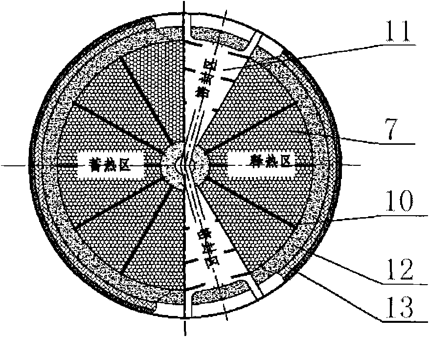
[0021] The upper hood is provided with a high-temperature flue gas inlet and a high-temperature air outlet, and a fire-resistant partition wall is provided between the high-temperature flue gas inlet and high-temperature air outlet, and an upper internal seal is provided between the fire-resistant partition wall and the...

specific Embodiment

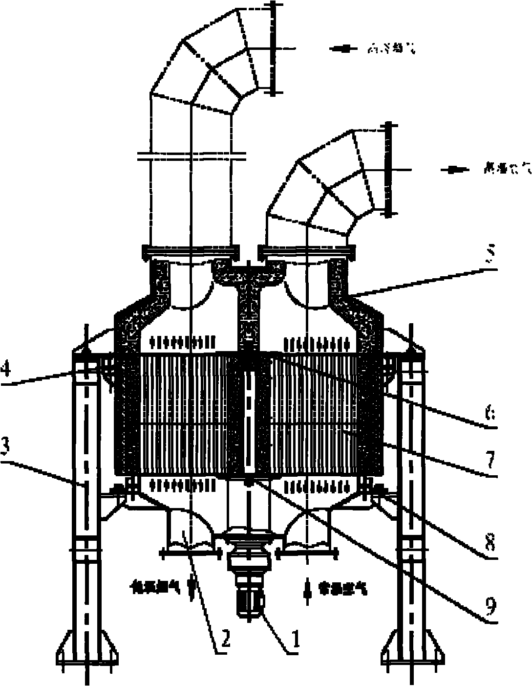
[0034] Such as figure 1 As shown, the equipment includes a driving device 1, a lower wind cover 2, an upper wind cover 5, a frame body 3, an upper water seal 4, a lower water seal 8, an upper inner seal 6, a lower inner seal 9, a heat storage body 7, etc. part.

[0035] The center of the bottom of the regenerator 7 is provided with a shaft extending out to connect with the drive device 1. The regenerator 7 is concentrically installed on the lower wind cover 2, driven by the drive device 1, and rotates at a constant speed between the lower wind cover 2 and the upper wind cover 5. , The lower windshield 2 and the upper windshield 5 are firmly connected with the frame body 3 .

[0036] The upper and lower hoods 2 and 5 are conical cylinder structures, and two pipe holes are symmetrically opened on the conical surface to discharge smoke and air respectively. A steel partition is set between the two pipe holes.

[0037] The outer seals between the upper and lower windshields 2 a...


PUM


Abstract

The invention discloses a continuous-rotation heat accumulating type air preheater comprising a cylindrical heat accumulating body, wherein the upper part and the lower part of the cylindrical heat accumulating body are respectively provided with an upper part fan cover and a lower part fan cover which are respectively fixed on a stand body, and the cylindrical heat accumulating body is connectedwith a rotary driving device; the upper part fan cover is provided with a high-temperature flue gas inlet and a high-temperature air outlet, and the lower part fan cover is provided with a low-temperature flue gas outlet and a normal-temperature air inlet which respectively correspond to the high-temperature flue gas inlet and the high-temperature air outlet; outer sealing is respectively arranged between the outer circumferences of the upper part fan cover and the lower part fan cover and the outer circumference of the cylindrical heat accumulating body, and the inner parts are provided withinner sealing. The continuous-rotation heat accumulating type air preheater can realize continuous and constant-temperature air supply and effectively simplifies a mechanism.

Description

technical field [0001] The invention relates to a thermal storage device, in particular to a continuous rotary thermal storage air preheater. Background technique [0002] The "High Temperature Air Combustion Technology (HTAC)" characterized by high efficiency, energy saving and environmental protection is widely used in the field of industrial furnaces and drives the sublimation of related professional technologies. It represents the technical status of the current high-temperature regenerative air preheater. [0003] In the prior art, the working principle of switching regenerative burners is that two regenerative burners are intermittently switched by a reversing valve to control the flow of high-temperature flue gas and normal temperature air to achieve alternate heat storage and release; The heat storage device achieves heat storage and release through the 180° fixed-axis rotation of the two heat storage bodies and intermittent switching, omitting the reversing valve. ...

Claims


Application Information

Patent Timeline
Patent Type & Authority Patents(China)
IPC IPC(8): F23L15/00
CPCY02E20/34
Inventor 吴道洪
Owner HUBEI SHENWU THERMAL ENERGY TECH
Why Eureka
Try Eureka