Spiral-tube heat exchanger

A tubular heat exchanger and spiral tube technology, applied in the field of spiral tube heat exchangers, can solve the problems of inability to achieve heat exchange enhancement at the same time, limited improvement of heat exchange capacity, and inability to fully exchange heat, etc., to achieve small installation space , Improve the heat exchange capacity and the effect of sufficient heat exchange

Inactive Publication Date: 2010-06-16
江秋良 +1
View PDF0 Cites 10 Cited by
  • Summary
  • Abstract
  • Description
  • Claims
  • Application Information

AI Technical Summary

Problems solved by technology

This type of heat exchanger does not form an independent closed channel on the outside of the spiral tube or bellows, but places the entire spiral tube or bellows part in the shell cavity for storing the heat exchange medium. The main purpose of the thread or corrugation is only By enlarging the heat exchange area and increasing the turbulence to strengthen the heat exchange on one side, the improvement of the heat exchange capacity per unit volume is limited, while the spiral wound tube heat exchanger forms independent channels on both sides, but Between the two fluids are two independent pipes in contact with each other through mechanical winding, the contact thermal resistance is large, and the heat exchange cannot be sufficient
[0003] Due to structural defects, the above-mentioned heat exchangers cannot achieve heat exchange enhancement on both sides at the same time to maximize the heat exchange capacity of the heat exchanger per unit volume, and cannot meet products with high requirements for space, such as: wall-mounted instant heating Heat exchange requirements for heat pump water heaters
It limits its application in the field of products that require high heat transfer per unit volume

Method used


Image

  • Spiral-tube heat exchanger
  • Spiral-tube heat exchanger
  • Spiral-tube heat exchanger

Examples


Embodiment Construction

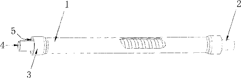
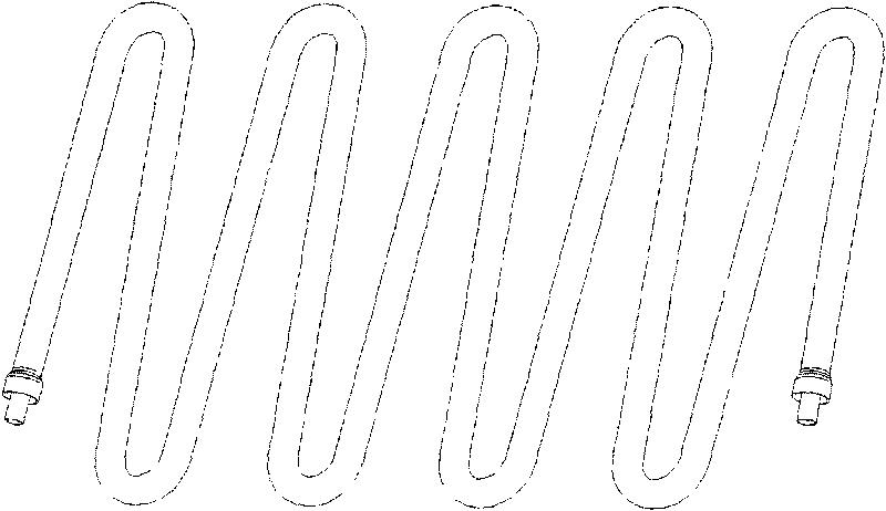
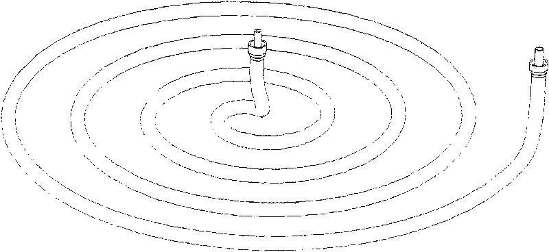
[0017] figure 1 It is a structural schematic diagram of the spiral tube heat exchanger of the present invention, consisting of figure 1 It can be seen that a spiral tube heat exchanger includes a refrigerant channel 5 and a water channel 4, and is characterized in that: the spiral tube 2 is placed inside the outer tube 1, and both ends are exposed, and the spiral tube 2 is placed on the outer tube 1. The pipe wall of the inner part of the pipe 1 is threaded, and the inner wall of the outer pipe 1 is matched with the thread crest of the outer wall of the spiral pipe 2, and connected together by brazing to form a sealing surface.

[0018] The inner wall of the spiral tube 2 is threaded.

[0019] Flared openings 3 are provided at both ends of the outer tube 1 .

[0020] The pipe wall thread of the spiral pipe 2 is a rectangular thread or a trapezoidal thread.

[0021] The screw channel formed by the brazing connection between the outer side of the spiral tube 2 and the inner s...


PUM


Abstract

The invention relates to a spiral-tube heat exchanger which comprises a refrigerant channel and a water channel, and is characterized in that a spiral tube is arranged inside an outer tube, and the two ends of the spiral tube are exposed outside; the tube wall inside the outer tube where the spiral tube is arranged takes on screw thread shape; and the inner wall of the outer tube is matched with crest of screw thread of the outer wall of the spiral tube, and the inner wall of the outer tube is connected with the crest of screw thread of the outer wall of the spiral tube into a whole by soldering, so that a sealing surface is formed. The inner wall of the spiral tube also takes on screw thread shape. The two ends of the outer tube are provided with flareouts. The water channel is arranged at the inner side of the spiral tube, and the refrigerant channel is positioned at a thread channel between the outer side of the spiral tube and the inner side of the outer tube. The spiral-tube heat exchanger has the advantages that refrigerant is contacted with water by a clapboard, so that the heat transfer efficiency is high, the thermal resistance is low, the flow path of the refrigerant can be greatly increased within a limited space, full heat exchange can be realized, and the heat exchange capability of the heat exchanger can be improved within a limited space. The spiral-tube heat exchanger can be widely applied to the products such as a wall hanging instant heating type heat pump water heater and the like which need smaller installation space and high unit volume heat exchange quantity.

Description

technical field [0001] The invention belongs to the technical field of heat exchangers, and relates to a spiral tube heat exchanger, in particular to a spiral tube heat exchanger with high heat exchange efficiency which can be used for heat pump water heaters. Background technique [0002] There are many kinds of enhanced heat exchange heat exchangers, such as spiral tube heat exchangers, corrugated tube heat exchangers, spiral wound tube heat exchangers, etc. This type of heat exchanger does not form an independent closed channel on the outside of the spiral tube or bellows, but places the entire spiral tube or bellows part in the shell cavity for storing the heat exchange medium. The main purpose of the thread or corrugation is only By enlarging the heat exchange area and increasing the turbulence to strengthen the heat exchange on one side, the improvement of the heat exchange capacity per unit volume is limited, while the spiral wound tube heat exchanger forms independen...

Claims


Application Information

Patent Timeline
Patent Type & Authority Applications(China)
IPC IPC(8): F28D7/10
Inventor 江秋良刘友明
Owner 江秋良
Why Eureka
Try Eureka