Working condition detecting method, device and system
A detection method and detection device technology, applied in the field of automation, can solve the problems of low reliability, low sensor sensitivity, short life, etc., and achieve the effect of improving reliability and sensitivity and avoiding complexity.
- Summary
- Abstract
- Description
- Claims
- Application Information
AI Technical Summary
Problems solved by technology
Method used
Image

Examples
Embodiment Construction
[0025] The technical solutions of the embodiments of the present invention will be further described below in conjunction with the accompanying drawings and specific embodiments.
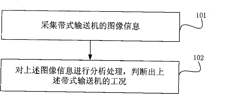
[0026] Such as figure 1 As shown, it is a flowchart of an embodiment of the working condition detection method of the present invention, and the method includes:
[0027] Step 101, collecting the image information of the belt conveyor;
[0028] Step 102 , analyzing and processing the above image information to determine the working condition of the above belt conveyor.
[0029] In the above step 101, the image information of the belt conveyor can be collected by setting a plurality of cameras above the belt conveyor; in the above step 102, the working conditions of the belt conveyor include many parameters, such as the belt conveyor Running speed, degree of deviation, degree of longitudinal tearing of the conveyor belt, distinction between smoke and dust, detection of stockpiling, detection of for...
PUM
 Abstract
Description
Claims
Application Information
PatSnap Eureka turns technology decisions into work you can execute. Powered by our Innovation Knowledge Graph, it runs expert workflows across engineering, life sciences, materials and intellectual property. Get your review-ready output in minutes.


