Binaural hearing instrument

A hearing aid, binaural technology, applied in hearing aids, electrical components, etc., can solve problems such as multi-space and power, inability to execute algorithms, etc.

Inactive Publication Date: 2010-06-16
OTICON
View PDF4 Cites 4 Cited by
  • Summary
  • Abstract
  • Description
  • Claims
  • Application Information

AI Technical Summary

Problems solved by technology

The disadvantage of this solution is that the circuitry in a unit with a signal processor requires substantially more space and power than in a unit without a signal processor
Another disadvantage of this solution is that the unit without signal processor cannot execute the algorithm when the connection to the unit with signal processor is cut off

Method used


Image

  • Binaural hearing instrument
  • Binaural hearing instrument

Examples


Embodiment Construction

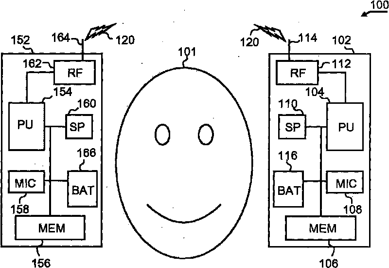
[0024] Figure 1a is a binaural hearing aid set, HI set 100, schematically shown in block diagram form as outlined above. The HI group 100 is arranged close to the ear of a human user 101 . The HI group includes a first unit 102 arranged on the left side of the user 101 (perceived from the user 101's perspective) and a second unit 152 arranged on the right side of the user 101 . It should be noted that HI group 100 may be of any type known in the art. For example, the HI group can be BTE (behind the ear), ITE (in the ear), RITE (receiver in the ear), ITC (in the ear canal), MIC (small ear canal), and CIC (deep ear canal), etc. any of the types. For the HI groups described here, it is essentially irrelevant in which type of implementation the specifically constructed circuits are implemented.

[0025] The block diagrams of the first and second units 102 and 152 turn out to be substantially the same, although alternative embodiments may include cases where either unit also in...


PUM


Abstract

A binaural hearing instrument set is described in which algorithms are split into a server part and a thin-client part. The respective server part of the algorithm is located in a first hearing instrument unit, while the thin-client part is located in a second unit in the binaural hearing instrument set. This is advantageous in that it enables optimization of the usage of combined processing resources in the two units.

Description

technical field [0001] The present invention relates to hearing aids and more particularly to a binaural hearing aid set comprising processing circuitry, memory circuitry and communication circuitry. Background technique [0002] Today's hearing aids have been developed as very small, lightweight and powerful signal processing units. Naturally, this is mainly due to the very advanced developments in miniaturization, power usage, etc. of electronic processing equipment during the past few decades. While earlier generations of hearing aids were predominantly of the analog type, today's technology in this field mainly involves digital processing units. Such a unit converts the audio signal from the audio input converter into digitally represented data which is processed with complex mathematical algorithms and then converted back to an analog signal and output to the user via the audio output converter. [0003] Transformation and processing algorithms are implemented by mean...

Claims


Application Information

Patent Timeline
Patent Type & Authority Applications(China)
IPC IPC(8): H04R25/00
CPCH04R25/554H04R25/552
Inventor S·B·格赖纳
Owner OTICON
Why Eureka
Try Eureka