Packaging method for combining telescopic screw with printed circuit board

A technology of printed circuit board and packaging method, which is applied in the direction of printed circuit, printed circuit manufacturing, printed circuit connected with non-printed electrical components, etc. Settings, technological advancements, easy-to-setup effects

Active Publication Date: 2012-01-11
王鼎瑞
View PDF0 Cites 0 Cited by
  • Summary
  • Abstract
  • Description
  • Claims
  • Application Information

AI Technical Summary

Problems solved by technology

[0003] Although the above-mentioned existing conventional method can combine the sleeve screw 5 in the perforation 71 of the printed circuit board 7, the sleeve screw 5 directly corresponds to the perforation 71 with its sleeve 53 when setting, and its screw head 51 and the sleeve 53 It cannot be compressed and fixed, so it needs to be placed manually, and the volume of the sleeve screw 5 and the hole diameter of the perforation 71 are small. Due to errors in manual placement, the flange 531 of the sleeve 53 cannot be aligned with the perforation 71 smoothly, resulting in poor pressing of the printed circuit board and damage to the board, and when the flange 531 of the sleeve 53 cannot be placed on the perforation 71 at one time , often due to the inaccurate plane precision of the printed circuit board 7, when the flange 531 of the sleeve 53 is set in the perforation 71, it cannot be completely pressed into the perforation 71, and it is easy to have deviation and skew.
In addition, it is necessary to press each sleeve screw 5 to assemble the sleeve screw 5 by pressing, so it is impossible to optimize the efficiency of assembling the sleeve screw 5 by using the surface adhesion technology widely used in the industry.
[0004] It can be seen that the above-mentioned existing packaging method of combining the sleeve screw with the printed circuit board obviously still has inconvenience and defects in method and use, and needs to be further improved urgently.
In order to solve the above-mentioned problems, the relevant manufacturers have tried their best to find a solution, but no suitable design has been developed for a long time, and the general method has no suitable method to solve the above-mentioned problems. This is obviously related. The problem that the industry is eager to solve

Method used


Image

  • Packaging method for combining telescopic screw with printed circuit board
  • Packaging method for combining telescopic screw with printed circuit board
  • Packaging method for combining telescopic screw with printed circuit board

Examples


Embodiment Construction

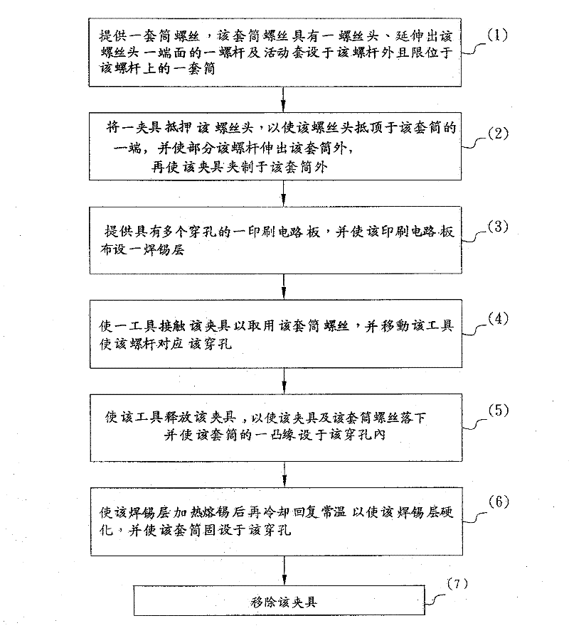
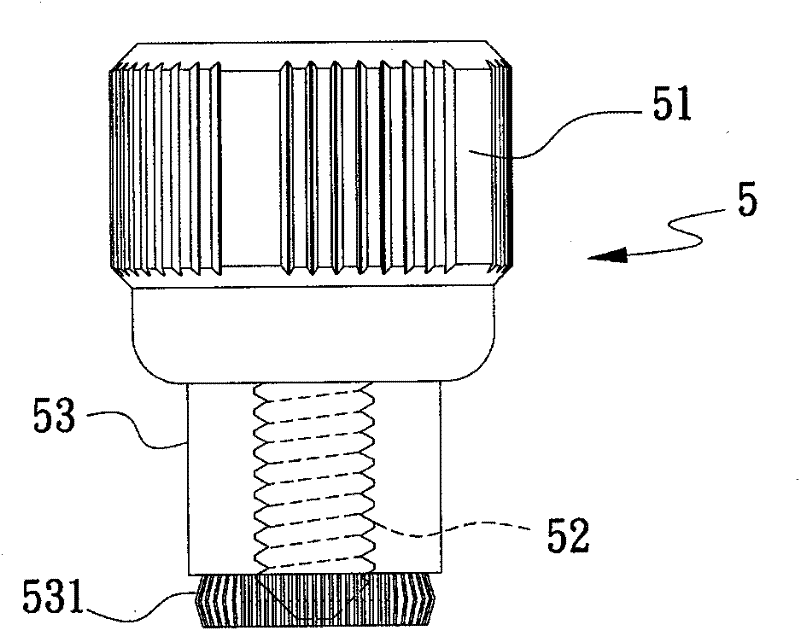
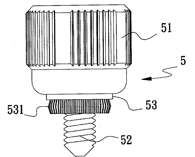
[0038] In order to further illustrate the technical means and effects adopted by the present invention to achieve the predetermined purpose of the invention, the following describes the specific implementation of the packaging method for combining sleeve screws with a printed circuit board according to the present invention with reference to the accompanying drawings and preferred embodiments. The methods, methods, steps, features and their effects are described in detail as follows.

[0039] The foregoing and other technical contents, features and effects of the present invention will be clearly presented in the following detailed description of the preferred embodiments with reference to the drawings. Through the description of the specific embodiments, a more in-depth and specific understanding of the technical means and effects adopted by the present invention to achieve the predetermined purpose can be obtained. However, the accompanying drawings are only for reference and...


PUM


Abstract

The invention relates to a packaging method for combining a telescopic screw with a printed circuit board, which comprises the following steps: pressing a screw head of the telescopic screw comprising the screw head, a screw rod and a sleeve with a fixture to prop the fixture at one end of the sleeve, providing the printed circuit board provided with a plurality of perforations and a solder layer; contacting the fixture with a tool to take the telescopic screw to make the screw rod correspond to the perforations of the printed circuit board; allowing the tool to release the fixture, and cooperating flanges of the sleeve with the solder layer to limit the flanges in the perforations; making the solder layer hardened to fix the sleeve. The package method achieves the effect of precisely and easily arranging the sleeve of the telescopic screw without shift and deflection.

Description

technical field [0001] The invention relates to a packaging method for combining a sleeve screw with a printed circuit board, in particular to a sleeve screw that can achieve precise, no offset, no skew and easy setting when the sleeve of the sleeve screw is set. A packaging method for screw bonding to a printed circuit board. Background technique [0002] Figure 1 to Figure 5 Schematic representation of socket screws respectively Figure 1 , indicating Figure II , Illustration of existing conventional packaging methods Figure 1 , indicating Figure II and signal Figure 3 Generally, when the conventional sleeve screw is combined on the printed circuit board, a sleeve screw 5 having a screw head 51, a screw 52 and a sleeve 53 is used, and the sleeve 53 of the sleeve screw 5 corresponds to a printed circuit board. Press down the screw head 51 on the through hole 71 of the circuit board 7 so that the serrated flange 531 of the sleeve 53 of the sleeve screw 5 is pressed...

Claims


Application Information

Patent Timeline
Patent Type & Authority Patents(China)
IPC IPC(8): H05K1/18H05K3/00
Inventor 王鼎瑞
Owner 王鼎瑞
Why Eureka
Try Eureka