Casing structure of electronic device

A technology for electronic devices and casings, which is applied to electrical equipment casings/cabinets/drawers, circuits, electrical switches, etc., can solve the problems of scrapped casings and inability to accurately fix key groups, and achieve the effect of speeding up production and maintenance.

Inactive Publication Date: 2010-06-16
INVENTEC CORP
View PDF0 Cites 14 Cited by
  • Summary
  • Abstract
  • Description
  • Claims
  • Application Information

AI Technical Summary

Problems solved by technology

[0005] In view of the above problems, the present invention provides a casing structure of an electronic device to improve the problem that the button set cannot be accurately fixed on the casing due to the use of hot-melt fixing method, and the casing is scrapped.

Method used


Image

  • Casing structure of electronic device
  • Casing structure of electronic device
  • Casing structure of electronic device

Examples


Embodiment Construction

[0041] Below in conjunction with accompanying drawing, structural principle and working principle of the present invention are specifically described:

[0042] The housing structure of the electronic device of the present invention, wherein the electronic device is a notebook computer (notebook), a display (diaplay), a camera, a mobile phone (mobile phone), a personal digital assistant (Personal Digital Assistant, PDA) or global satellite positioning System (Global Positioning System, GPS) and other devices with key operation. The above is only used for illustration and is not limited thereto. In the following, a notebook computer will be used as an embodiment of the present invention for illustration.

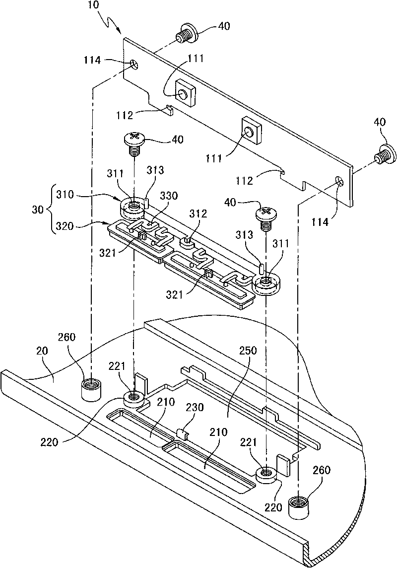
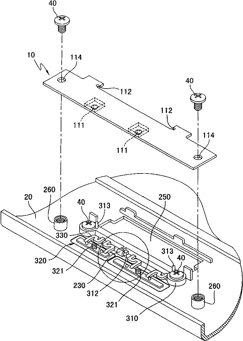
[0043] see figure 1 As shown in the schematic diagram of the first embodiment of the present invention, the casing structure of the electronic device of the present invention is applied to an electronic device having a circuit board 10, and the circuit board 10 has two micro...


PUM


Abstract

A casing structure of an electronic device comprises a shell, a key group and at least one fixing part, wherein the shell is provided with a fixing column which is provided with a fixing hole; the key group has a support part, the support part is provided with a positioning hole corresponding to the fixing hole; and the key group is embedded on the shell through the fixing hole. Therefore, the key group can be fixedly arranged on the shell by using the fixing part for arranging in the fixing hole and butting the support part.

Description

technical field [0001] The invention relates to a casing structure of an electronic device, in particular to a casing structure of an electronic device with keys. Background technique [0002] With the vigorous development of the electronic industry, various electronic products have been widely used in daily life. Among these electronic products, portable electronic devices are especially favored by users due to their characteristics of being convenient to carry and easy to operate. Generally, most portable electronic devices have a signal control device for moving the cursor on the display of the portable electronic device. The small computer is equipped with a touchpad and a key set matched with the touchpad. When the user slides his finger on the surface of the touchpad, he can control the position of the cursor on the display and cooperate with the pressing point of the key set. Select operation, so that the user can easily complete the operation and click function of ...

Claims


Application Information

Patent Timeline
Patent Type & Authority Applications(China)
IPC IPC(8): H05K5/00H01H13/02
Inventor 王百禄陈家震何承泰黎耀伟刘政嵘
Owner INVENTEC CORP
Why Eureka
Try Eureka