

A sander used in particular for sanding of flat, concave, and convex surfaces and the method of its utilisation
A grinding machine, convex technology, used in grinding machines, portable grinding machines, grinding/polishing equipment, etc.
- Summary
- Abstract
- Description
- Claims
- Application Information
AI Technical Summary
Problems solved by technology
Method used
Image

Examples
example 1
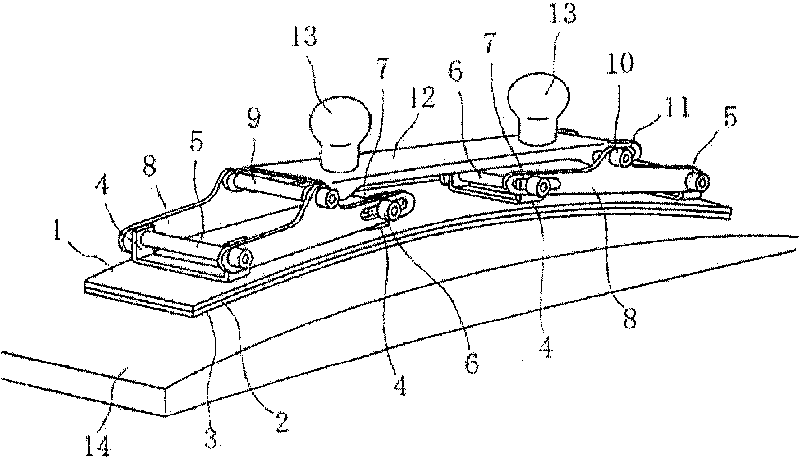
[0037] A sander or more precisely a hand sanding plane (see FIG. 1 ) comprises a substantially flexible pressure plate 1 on the bottom of which is mounted sponge rubber 2 and a dry zipper 3 for attaching sandpaper. Bracket 4 is positioned on the pressure plate with pins 5 and 6 . The brackets are connected in pairs by balance bars 8 provided at one end with openings for pins 5 and at the other end with notches 7 in which the pins 6 move. Said movement is caused by any deflection of the pressure plate 1 and causes a change in the distance between the pins 5 and 6 . Balance pole 8 includes pins 9 and 10 . The balance bars 8 are bridged mutually by a balance bar 12 provided at one end with an opening for the pin 9 and at the other end with a notch 11 in which the pin 10 moves and passes through the balance bar 8 hole. The function of the balance bars 8 and 12 is to evenly distribute the pressure applied to the handle of the grinding plane along the entire length of the pressur...
example 2
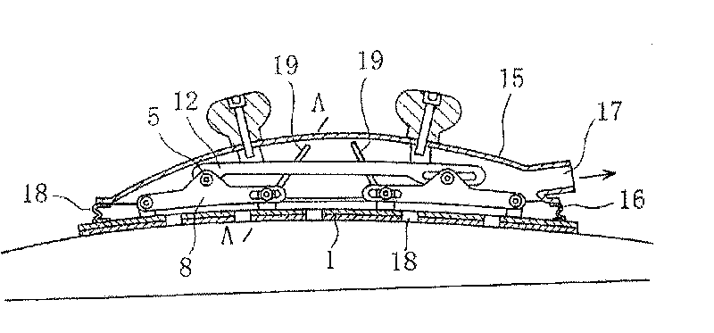
[0039] The manual sanding plane (see Figure 2) has a similar construction to the plane described above (see Figure 1). The manual sanding plane is attached with a strong plastic cover 15 with a flexible collar 16 and a coupling 17 for connecting a rubber hose for extracting the abrasive dust. For this purpose, there are through holes 18 in the pressure plate for extracting abrasive dust. The pressure plate is also provided with tie rods 19 fixed relative to the upper balance bar and thus able to fix the bending of the pressure plate.
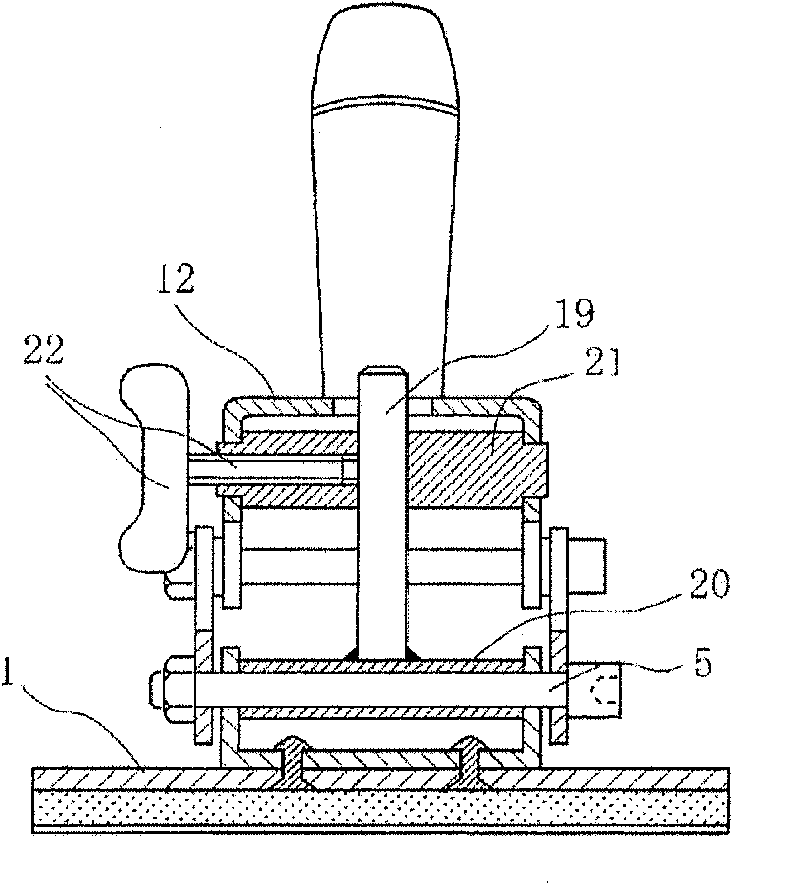
[0040] The detailed function and structure of the balance bar 19 will be apparent from section AA in FIG. 3 . The tube 20 is firmly connected to the balance bar 19 , which rests pivotally on the pin 5 . At the same time, the balance bar 19 passes freely through a lateral opening in the pin 21 placed pivotally over the upper balance bar or, more precisely, over the handle of the grinder 12 . On the longitudinal axis of this pin 21 is a threade...
example 3
[0043] A linear mechanical sander with a flexible pressure plate (see Figure 3) is based on a similar structure and principle to the manual sanding plane (see Figures 1 and 2). In addition, the flexible pressure plate 29 is fitted with a mechanically driven movable shaped plate 27 which has an abrasive material 28 mounted on its bottom. Said plate is designed as a C-shaped profile partially enclosing the flexible pressure plate 29 . Figures 9 and 10 show views and cross-sections of the thus formed movable sanding plate surrounding the flexible pressure plate. The profile of the movable sanding plate 27 is lightened on its top side due to lateral notches 31 formed at fixed intervals, which remove the longitudinal rigidity of the profile. Details of the lightened portion are illustrated in FIG. 11 . Figure 12 illustrates the principle and state of the relief profile 27 towards the pressure plate 29 during concave or convex flexing of the plate. The described configuration of ...
PUM
 Abstract
Description
Claims
Application Information