PWM rectifier control method and device

A control method and technology of a control device are applied in the output power conversion device, the conversion of AC power input to DC power output, electrical components, etc. For problems with high frequency, the effect of flexible constraint mode, simple control algorithm and fast response speed can be achieved.

Active Publication Date: 2019-12-06
ZHUZHOU CSR TIMES ELECTRIC CO LTD
View PDF7 Cites 0 Cited by
  • Summary
  • Abstract
  • Description
  • Claims
  • Application Information

AI Technical Summary

Problems solved by technology

In this scheme, the prediction and optimization mode is the correction of the optimal control, which is convenient for modeling; the rolling optimization strategy is adopted to make up for the uncertainty caused by model mismatch, distortion, interference, etc. in time, which improves the immunity and adaptability However, because there is no fixed switching frequency and the switching frequency is high, it is difficult to obtain engineering applications in high-power PWM rectifiers
[0007] The patent application number is 201610983876.1, and the title is "A Torque Control Strategy for Permanent Magnet Synchronous Motor Based on Flux Vector", which is the background technology document of this application. In order to reduce the switching frequency and reduce the loss, the document calculates and uses another value function to maximize The optimal duty cycle of each alternative voltage vector in one hour is used to realize the torque control strategy based on the flux linkage vector. However, since the switch combination is still updated in each prediction period, the reduction of the switching frequency by this method is very limited.
[0008] The defects in the prior art mainly include: 1. Each calculation outputs an optimal switch combination. When the prediction period is small, the switching frequency will be too high; 2. The method of prolonging the prediction period can reduce the switching frequency. However, when the prediction period is lengthened, it will cause an increase in harmonics, which will affect the control performance of the system

Method used


Image

  • PWM rectifier control method and device
  • PWM rectifier control method and device
  • PWM rectifier control method and device

Examples


Embodiment Construction

[0057] The present invention will be further described below with reference to the accompanying drawings and specific preferred embodiments, but the protection scope of the present invention is not limited thereby.

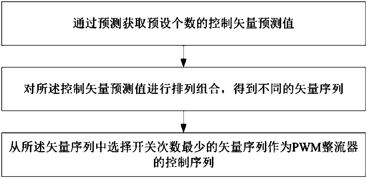
[0058] like figure 1 As shown, the PWM rectifier control method of the present embodiment includes the following steps: S1. obtaining a preset number of control vector predicted values ​​through prediction; S2. arranging and combining the control vector predicted values ​​to obtain different vector sequences; S3. From the vector sequences, the vector sequence with the least number of switches is selected as the control sequence of the PWM rectifier.

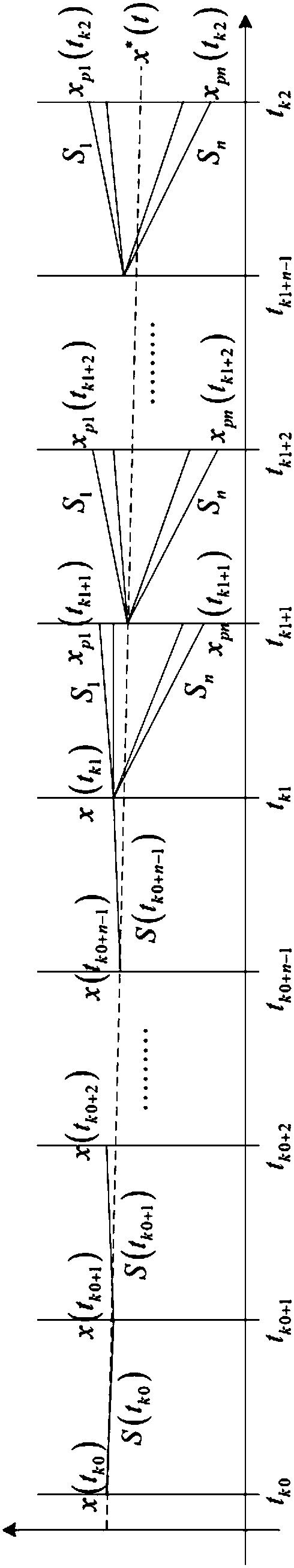
[0059] In this embodiment, the specific steps of step S1 include: S1.1. Calculate the output of the current action period according to the output of the previous action period and the control vector predicted value of the current action period through a preset prediction model; S1. 2. Through the preset prediction m...


PUM


Abstract

The invention discloses a PWM rectifier control method and device. The method comprises the following steps: S1, obtaining a preset number of control vector predicted values by prediction; S2, permutating and combining the control vector predicted values to obtain different vector sequences; S3, selecting, from the vector sequences, a vector sequence with least switching times as a control sequence of a PWM rectifier. The method is able to limit the switching frequency of a system under the condition that the prediction period is not changed, and can ensure the dynamic performance of the system, is simple and fast in response, and has a flexible processing system constraint.

Description

technical field [0001] The present invention relates to the technical field of PWM rectifier control, in particular to a PWM rectifier control method and device. Background technique [0002] Control the DC side voltage to maintain the constant DC bus voltage. Its output is used as the AC current (or power) command of the AC current (or power) inner loop, and the AC current (or power) inner loop is used to quickly and timely adjust the AC side. current, suppress the influence of load disturbance, enable the actual AC current to quickly track the AC current command, and achieve unity power factor control. In the double-loop control, the voltage outer loop and the current (or power) inner loop must cooperate in speed, and the outer loop is much slower than the inner loop. This type of control mainly includes Voltage Oriented Vector Control (VOC) and Direct Power Control (DPC). [0003] Nowadays, VOC is one of the widely used control strategies in PWM rectifier control. The s...

Claims


Application Information

Patent Timeline
Patent Type & Authority Applications(China)
IPC IPC(8): H02M7/217H02M1/088
CPCH02M1/088H02M7/217
Inventor 尚敬张少云佘岳徐凤星盛建科谭宇戴茜茜黄禹文彭韬江海啸
Owner ZHUZHOU CSR TIMES ELECTRIC CO LTD
Why Eureka
Try Eureka