
Tower plate bearing structure of large-scale cross-flow plate type tower

A support structure and cross-flow plate technology, applied in the field of plate towers, can solve the problems of low efficiency, space utilization, and mass transfer area of ​​cross-flow plate towers, so as to reduce stagnation area and liquid back-mixing, improve The efficiency of the whole tower and the effect of uniform liquid flow distribution

Active Publication Date: 2013-08-28
TIANJIN UNIVTECH CO LTD
View PDF7 Cites 0 Cited by
  • Summary
  • Abstract
  • Description
  • Claims
  • Application Information

AI Technical Summary

Problems solved by technology

[0003] In the prior art, each tray of the tray tower is supported by cross-beams of sufficient strength, and the cross-sectional height of each cross-beam of sufficient strength will inevitably cause an excessive gas-liquid separation zone and downcomer zone between the two trays. , which reduces the space utilization rate in the tower, which is equivalent to reducing the mass transfer area, so the efficiency of the existing cross-flow plate tower is low, and the cost of the tower is also increased

Method used


Image

  • Tower plate bearing structure of large-scale cross-flow plate type tower
  • Tower plate bearing structure of large-scale cross-flow plate type tower
  • Tower plate bearing structure of large-scale cross-flow plate type tower

Examples


Embodiment Construction

[0018] The present invention will be described in detail below in conjunction with the embodiments and accompanying drawings.

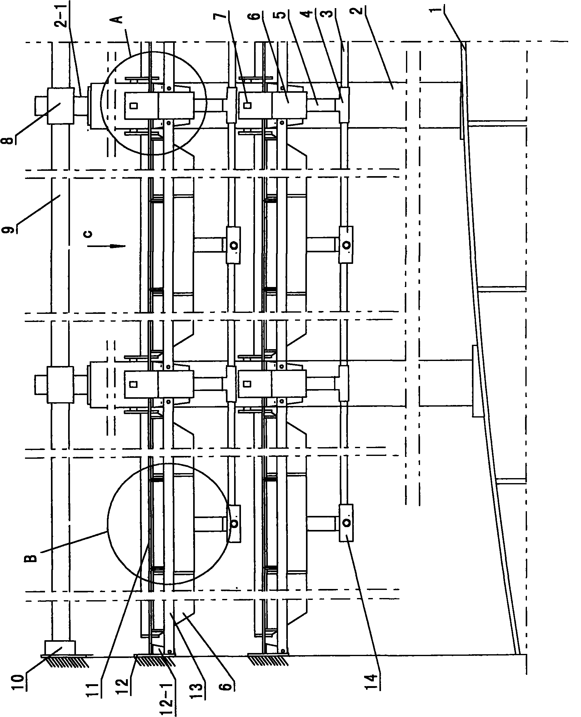
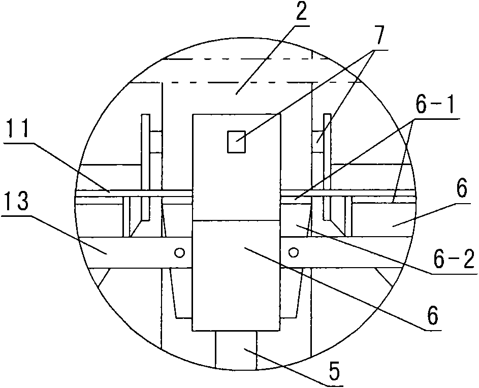
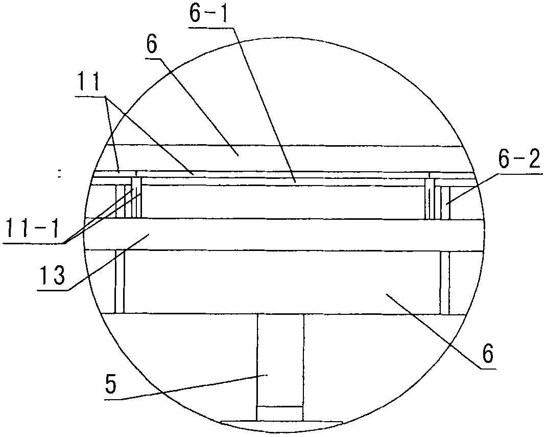
[0019] Following embodiment is the tray support structure of 12 meters tower diameter tray tower, figure 1 It is the supporting structure of its two-layer partial tray.

[0020] Such as figure 1 As shown, the load-bearing supports 1 at the bottom of the tower are distributed at equal intervals and fixed with 21 columns 2, each column is a square tube, and the end shaft 2-1 at the top is provided with a shaft sleeve 8 slidingly engaged therewith, and each shaft sleeve 8 Horizontal pull rods 9 are arranged between each bushing 8 and the tower wall located at the periphery. The so-called peripheral axle sleeves refer to the axle sleeves closest to the tower wall. One end of the horizontal tie rod 9 between the peripheral axle sleeves 8 and the tower wall of the embodiment is fixed to the connecting seat 10 of the tower wall.

[0021] The load-bearing ...


PUM


Abstract

The invention discloses a tower plate bearing structure of a large-scale cross-flow plate type tower. Shaft sleeves are arranged on the upper ends of various upright posts at the bottom of the tower; pull rods are arranged among various shaft sleeves; liquid-receiving long grooves are supported in layers among the upright posts and between the upright post and a tower wall; the upright posts are supported at the two ends of the groove in a sliding mode; one end of the liquid-receiving long grooves between the upright posts and the tower wall is fixed with a tower ring; supporting unit tower plates are respectively arranged between each layer of the liquid-receiving long grooves and the tower ring; the layered tower plate consists of unit tower plates; and each unit tower plate is provided with gas lifting pores; liquid-outlet boxes are arranged above central parts of each unit tower plate of each layer of the tower plate arranged below the top layer of the tower plate; the periphery and the bottom of the liquid-outlet box are provided with liquid-outlet holes; and each liquid-outlet box is respectively provided with pipelines which are adjacently communicated with the groove bottom of the upper layers of each liquid-receiving long groove. The tower plate bearing structure overcomes the defect that a space between the tower plates caused by supporting beams of the traditional tower plates is oversize, thereby ensuring enough rigidity support of multiple upper layer and lower layer of tower plates, satisfying liquid-distribution and separation requirements, and being favorable to improving the whole-tower effect and reducing the cost of the tower.

Description

technical field [0001] The invention belongs to a tray tower, in particular to a tray supporting structure of a large cross-flow tray tower. Background technique [0002] The mass transfer of the cross-flow plate column is realized by the rising gas passing through the plate and contacting the liquid on the plate. The mass transfer and heat transfer usually only occur on the plate, and the liquid pool area on the plate is the gas-liquid transfer. The mass area, above the liquid pool is the gas-liquid separation area and the downcomer area, which resolves most of the entrained gas and makes the liquid fully mixed and then redistributed into the next layer of trays, which belongs to the step-by-step contact mass transfer. [0003] In the prior art, each tray of the tray tower is supported by cross-beams of sufficient strength, and the cross-sectional height of each cross-beam of sufficient strength will inevitably cause an excessive gas-liquid separation zone and downcomer zon...

Claims


Application Information

Patent Timeline
Patent Type & Authority Patents(China)
IPC IPC(8): B01D3/16
Inventor 宋光复萧波田桂林金浩禹萧庆融
Owner TIANJIN UNIVTECH CO LTD
Learn More