Power-driven motion device

A motion device, power-driven technology, applied in transportation and packaging, motor vehicles, body and other directions, can solve problems such as non-compliance with the development trend of environmental protection and energy saving, energy consumption, etc.

Inactive Publication Date: 2010-06-23
朱晓义
View PDF0 Cites 10 Cited by
  • Summary
  • Abstract
  • Description
  • Claims
  • Application Information

AI Technical Summary

Problems solved by technology

[0002] For existing power-driven motion devices, such as automobiles, trains, ships, etc., when moving at high speed, the housing of the motion device will directly hit the front or side resistance fluid (such as water or air flow), in order to reduce the motion The resulting resistance generally sets a streamlined surface on the shell, but this is a direct collision at the cost of huge energy consumption, which does not conform to the current development trend of environmental protection and energy saving

Method used


Image

  • Power-driven motion device
  • Power-driven motion device
  • Power-driven motion device

Examples


Embodiment Construction

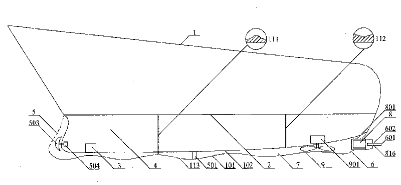
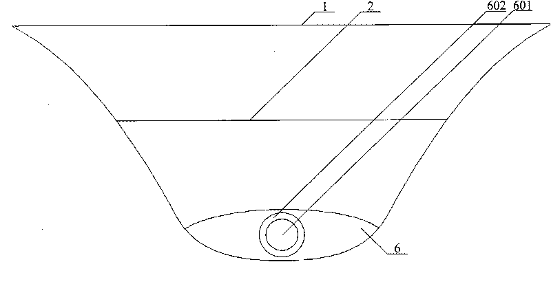
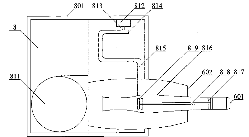
[0035] like Figure 1 to Figure 4As shown, it is the first embodiment of the present invention, and the motion device is a ship. The hull 1 of the ship located below the water level 2 includes an outer shell 101 and an airtight inner shell 102 . The front end of the housing 101 has an inlet 5, and the inlet 5 is provided with a parabolic rotating head 503 and a motor 504 that drives the rotating head 503 to rotate at a high speed. The rotating head 503 throws the fluid away to reduce the direct impact of the fluid on the inner casing 102 The resulting drag effect. The housing 101 has a spoiler surface 113 . The inner shell 102 and the outer shell 101 are separated by a certain distance by the fluid layer channel 7, the inlet 5 is set at the front end of the outer shell 101, and the rear end of the outer shell 101 has an outlet 6, and the fluid layer channel 7 communicates with the inlet 5 and the outlet 6. Microwave motor 8 is arranged in the outlet 6, and microwave motor 8...


PUM


Abstract

The invention discloses a power-driven motion device with a casing which is internally provided with at least one vibrator capable of vibrating the casing and forming a vibration wave layer outside the casing. The motion device is similar to a power-driven underwater motion device (comprising a water surface motion and an underwater motion device), such as ship, submarine, underwater missile, torpedo, etc.; the motion device can also be land transportation means, such as train, car, etc. or aerial transportation means, such as aircraft, airship, etc.. The vibration wave layer, generated by means of the vibration of the vibrator along with the casing, surrounds the casing of the motion device so that huge fluid resistance avoids the motion device naturally after the collision with the vibration wave layer, as a result, the motion device travels in an ideal state, namely under quite small fluid resistance, thereby greatly enhancing the motion speed of the motion device and saving energy.

Description

technical field [0001] The present invention relates to a sports device, in particular to a sports device driven by power and capable of moving in air or water (water surface or underwater). Background technique [0002] For existing power-driven motion devices, such as automobiles, trains, ships, etc., when moving at high speed, the housing of the motion device will directly hit the resistance fluid (such as water flow or air flow) in the front or side, in order to reduce the motion The resulting resistance is generally provided with a streamlined surface on the housing, but this is a direct collision at the cost of huge energy consumption, which does not conform to the current development trend of environmental protection and energy saving. Contents of the invention [0003] The technical problem to be solved by the present invention is to overcome the deficiencies of the prior art and provide an exercise device capable of effectively reducing resistance during exercise....

Claims


Application Information

Patent Timeline
Patent Type & Authority Applications(China)
IPC IPC(8): B63H19/00B63G8/08B63G8/28B62D37/02B64D27/02
Inventor 朱晓义
Owner 朱晓义
Why Eureka
Try Eureka