
Main shaft neck part oil return mechanism of driving shaft of scroll compressor

A scroll compressor and compression mechanism technology, applied in the field of scroll compressors, can solve the problems of rising manufacturing costs, difficult operations, and many processing procedures, and achieve the effects of reducing processing costs, avoiding rising manufacturing costs, and reducing assembly requirements.

Inactive Publication Date: 2010-06-23
MIDEA GRP CO LTD
View PDF2 Cites 8 Cited by
  • Summary
  • Abstract
  • Description
  • Claims
  • Application Information

AI Technical Summary

Problems solved by technology

[0007] However, this method has many processing steps, resulting in increased manufacturing costs.
Secondly, due to its structural characteristics, there is a clear direction requirement for bearing installation. In actual use, once the installation is wrong, the entire component including the frame will be scrapped, resulting in a further increase in manufacturing costs.
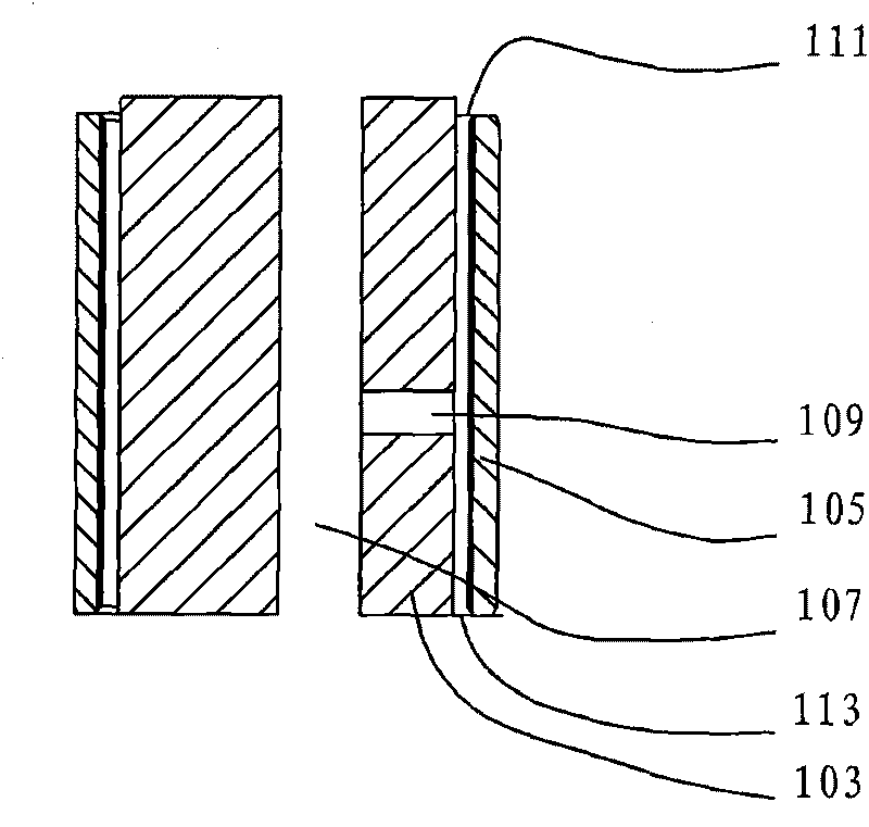
In addition, this technology does not specify the specific location of the annular oil tank, and it is difficult to operate in practice

Method used


Image

  • Main shaft neck part oil return mechanism of driving shaft of scroll compressor
  • Main shaft neck part oil return mechanism of driving shaft of scroll compressor
  • Main shaft neck part oil return mechanism of driving shaft of scroll compressor

Examples


Embodiment Construction

[0023] The present invention will be further described below in conjunction with the accompanying drawings and embodiments.

[0024] see Figure 4 , the scroll compressor, the compression mechanism part 2 and the motor part 7 are connected through the drive shaft 5 , that is, the crankshaft, and accommodated in the airtight container 1 . The compression mechanism part 2 is composed of a fixed scroll 4 , a movable scroll 3 , a frame 6 , a drive shaft 5 and an Oldham ring 8 as main components.

[0025] The fixed scroll 4 has an end plate 4b and a spiral fixed scroll 4a standing upright on the end plate 4b. The fixed scroll 4 is fastened on the upper side of the frame 6 by screws. The periphery of the frame 6 is fixed on the airtight container 1, and at the bottom of the airtight container 1, there is a main bearing 16 supporting the rotation of the drive shaft 5.

[0026] The airtight container 1 includes an upper casing 20 , a main casing 21 and a lower casing 22 connected i...


PUM


Abstract

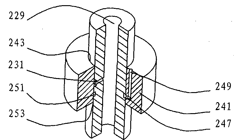
The invention relates to a main shaft neck part oil return mechanism of a driving shaft of a scroll compressor. The scroll compressor comprises a compression mechanism part and a motor part which are arranged in a sealing container, wherein the compression mechanism part comprises a movable eddy disc and a machine frame, the movable eddy disc is connected with a static eddy disc, the machine frame is used for supporting the movable eddy disc and the driving shaft, the back side of the movable eddy disc is provided with a driving part, the driving shaft is connected with the driving part of the movable eddy disc through a driving bearing, the driving shaft is connected with the machine frame through a main bearing, the upper end surface of the machine frame and the back side of the eddy disc form a space for accommodating the driving part of the movable eddy disc, the space is also simultaneously used as an oil recovery cavity for lubricating oil from the driving bearing and the main bearing, an annular oil groove is formed at one end of the main shaft neck part of the driving shaft far away from the movable eddy disc, an oil path is arranged on the outer wall of the main shaft neck part, and the oil path is communicated with the annular oil groove and the oil recovery cavity. The invention has the characteristics that the manufacture cost is low, the sufficient oil return at the main shaft neck part can be ensured, and the discharge of the lubricating oil along with the high-pressure gas can be reduced.

Description

technical field [0001] The invention relates to a scroll compressor, in particular to an oil return mechanism of the main neck of the drive shaft of the scroll compressor. Background technique [0002] Scroll compressors have been widely used in the field of refrigeration and air conditioning. Among the main structures of scroll compressors that have been announced, low-pressure structures and high-pressure structures are mainly used. Due to its advantages in the field of frequency conversion, high-pressure structural compressors have received more and more attention in product development. [0003] As disclosed in Patent Document 1: Japanese Patent Document No. Unexamined Patent Publication No. Hei 9-79153, this type of compressor accommodates a scroll-type compression mechanism and a motor in a sealed casing, and the compression mechanism is connected to the motor by a drive shaft. A bearing is provided between the compression mechanism and the motor. On the other hand, t...

Claims


Application Information

Patent Timeline
IPC IPC(8): F04C29/02F04C18/02
Inventor 邵海波
Owner MIDEA GRP CO LTD
Learn More