
Aqueous joint seal structure

A technology of sealing structure and water joint, which is applied in the direction of engine sealing, engine components, mechanical equipment, etc., can solve the problems of large sealing friction resistance torque, short life of sealing ring, low sealing pressure resistance, etc., and achieve the increase of sealing pressure resistance , the effect of reducing frictional power consumption and increasing reliability

Inactive Publication Date: 2010-06-23
BEIJING JIAOTONG UNIV
View PDF0 Cites 3 Cited by
  • Summary
  • Abstract
  • Description
  • Claims
  • Application Information

AI Technical Summary

Problems solved by technology

[0003] The purpose of the present invention is to overcome the deficiencies of the existing water joint seal ring seal friction resistance torque, short seal ring life, seal failure due to wear or corrosion of the seal ring, and low seal pressure resistance, and to provide a water joint seal structure

Method used


Image

  • Aqueous joint seal structure
  • Aqueous joint seal structure
  • Aqueous joint seal structure

Examples


Embodiment Construction

[0017] The present invention will be further described in conjunction with accompanying drawing:

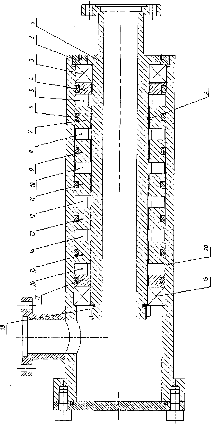
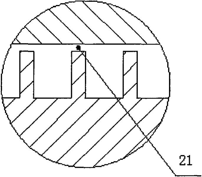
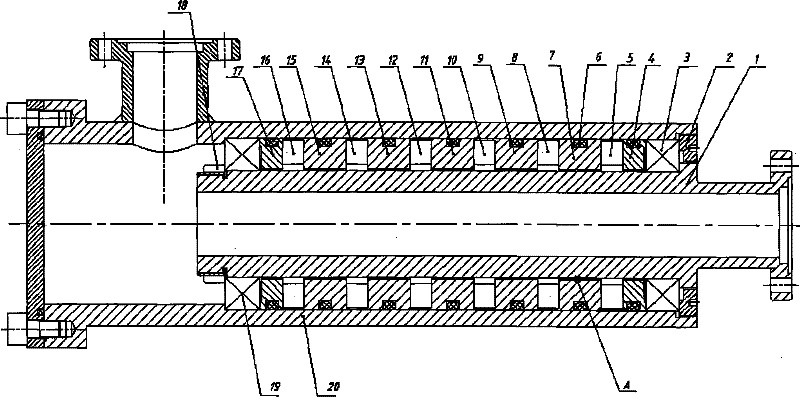
[0018] A water joint sealing structure, such as figure 1 , which consists of a hollow shaft and seal assembly supported in two bearings mounted within a housing. The sealing assembly consists of a right small pole piece 4, a first magnet 5, a first large pole piece 7, a second magnet 8, a second large pole piece 9, a third magnet 10, a third large pole piece 11, and a fourth magnet 12. , the fourth large pole piece 13, the fifth magnet 14, the fifth large pole piece 15, the sixth magnet 16, and the left small pole piece 17 are bonded in sequence;

[0019] After injecting magnetic liquid into the inner holes of the first magnet 5, the second magnet 8, the third magnet 10, the fourth magnet 12, the fifth magnet 14 and the sixth magnet 16, install the sealing assembly on the left bearing 3 and the right bearing 19 between;

[0020] The sealing assembly is fixed on the hollow shaf...


PUM


Abstract

The invention relates to an aqueous joint seal structure comprising a hollow shaft and a seal assembly, wherein the seal assembly comprises a small right pole piece (40), a first magnet (5), a first large pole piece (7), a second magnet (8), a second large pole piece (9), a third magnet (10), a third large pole piece (11), a fourth magnet (12), a fourth large pole piece (13), a fifth magnet (14), a fifth large pole piece (15), a sixth magnet (16) and a small left pole piece (17) which are sequentially adhered; after magnetic liquid is injected into an inner hole from the first magnet (5) to the sixth magnet (16), the seal assembly is arranged between a left bearing (3) and a right bearing (19) and is fixed with the hollow shaft (1) by lock nuts (18); and the hollow shaft (1) provided with the seal assembly is arranged in a shell (20) and is connected with screw threads of the shell (20) through a nut (2). The invention overcomes the defects of large frictional resistance moment, short service life, poor sealing and low pressurization of the existing seal structure.

Description

technical field [0001] The invention relates to a sealing structure, which is especially suitable for sealing water joints. Background technique [0002] At present, the sealing structure of the water joint basically adopts the traditional seal ring seal. All types of seal ring seals are contact packing seals. Trapezoidal grooves are processed on the stationary parts, and the seal rings are made into rings or strips according to standards. , placed in the trapezoidal groove in close contact with the shaft to play a sealing role. There are many problems in the seal ring sealing, such as large frictional resistance moment, short life of the seal ring, low sealing reliability, and the seal ring is easily corroded by water, resulting in seal failure. Contents of the invention [0003] The purpose of the present invention is to overcome the disadvantages of the existing water joint seal ring, such as large seal frictional resistance torque, short seal ring life, seal failure d...

Claims


Application Information

Patent Timeline
Patent Type & Authority Applications(China)
IPC IPC(8): F16J15/53
Inventor 李德才陈燕
Owner BEIJING JIAOTONG UNIV
Learn More