

Secure self-radiating LED lamp device
A self-radiating technology for LED lamps, which is applied to lampshades, lighting and heating equipment, and cooling/heating devices for lighting devices. Improve cooling effect and reduce cost
- Summary
- Abstract
- Description
- Claims
- Application Information
AI Technical Summary
Problems solved by technology
Method used
Image

Examples
example example 1
[0025] Example 1 (natural cooling type)
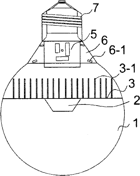
[0026] Such as diagram 2-1 The self-heating type LED lamp shown is a creative improvement to the existing known and commonly used LED lamps.
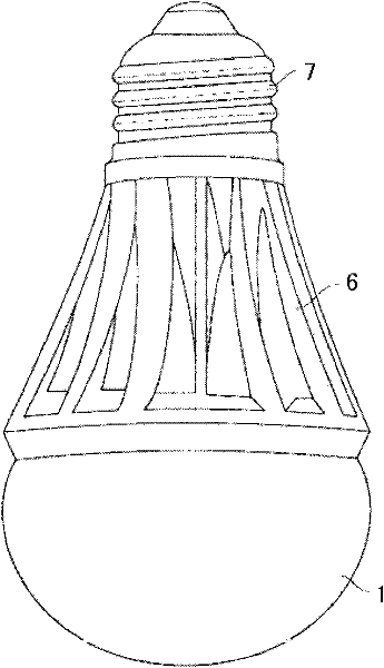
[0027] This self-heating LED lamp includes an external power connector 7, a lamp cup 6, an internal power converter 5, a radiator 3, an LED light source 2, and a lampshade 1, and the internal power converter 5 has cooling fins 3- The radiator 3 of 1 is installed in the lower part of the inner cavity of the lamp cup 6, and the external power connector, the lamp cup, the internal power converter, the radiator, and the LED light source are connected through connectors to form the entire lamp. The said radiating fin 3- 1 The radiator 3 is installed in the inner cavity of the lamp cup 6, or the upper part of the lampshade 1, or in the inner cavity of the junction of the lamp cup 6 and the lampshade 1, and the LED light source 2 is installed in the bottom of the radiator near the lampshade 1. In th...
Embodiment 2
[0029] Embodiment 2 (enhanced cooling type)
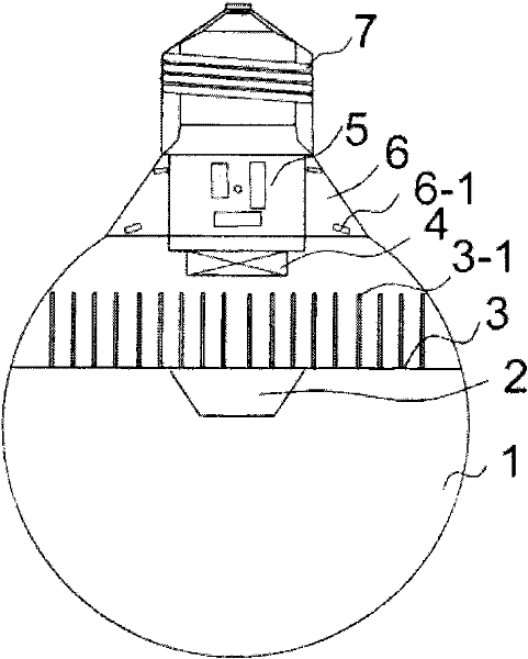
[0030] For LED light source lamps with large luminous power (see Figure 2-2 ), in addition to adopting the basic structure of Embodiment 1 in the basic structure: external power connector 7, lamp cup 6, internal power converter 5, radiator 3, LED light source 2, lampshade 1, wherein the internal power converter 5, The radiator 3 with heat dissipation fins 3-1 is installed in the lower part of the inner cavity of the lamp cup 6, and the external power connector, lamp cup, power converter, radiator, and LED light source are connected through the connecting piece to form the entire lamp. Radiating fins 3-1 The radiator 3 is installed in the inner cavity of the lamp cup 6, or the upper part of the lampshade 1, or in the inner cavity of the junction of the lamp cup 6 and the lampshade 1, and the LED light source 2 is installed on the bottom of the radiator. At the lower part of one side of the lampshade 1, a micro-fan 4 is added at th...
Embodiment 3
[0032] In practical application, for LED lamps with low power, the radiator 3 may not be a flat metal sheet with cooling fins 3-1, and it can be directly installed on the lamp cup 6 with the ventilation hole 6-1. Or the inner cavity of the lampshade utilizes the ventilation hole 6-1 to generate a "revolving lantern" effect to dissipate heat naturally.
PUM
 Abstract
Description
Claims
Application Information