
Spare automatic switching comprehensive tester

A technology of comprehensive tester and equipment self-injection, which is applied in the direction of instruments, measuring electricity, measuring devices, etc., can solve the problems of time-consuming and laborious inspection, cumbersome methods, and complicated test wiring, etc., to improve the reliability of power supply, improve power quality, and reliable The effect of action

Inactive Publication Date: 2010-06-23
JIANGSU ELECTRIC POWER COMPANY YANGZHOU POWER
View PDF0 Cites 19 Cited by
  • Summary
  • Abstract
  • Description
  • Claims
  • Application Information

AI Technical Summary

Problems solved by technology

The reliability and correctness of the logic of the standby automatic switching device and its circuit cannot be guaranteed
[0005] At present, there are domestic methods for testing the automatic input device of the backup power supply, which are cumbersome, the test wiring is complicated, the test flexibility is poor, the test is time-consuming and laborious, and the test effect is not ideal, and it cannot completely simulate various states that may actually occur. The simulated circuit breaker used is also Unable to simulate the sneak tripping or refusal state of the circuit breaker well, no main transformer failure simulation equipment
Make it impossible to comprehensively detect the state of the device under test

Method used


Image

  • Spare automatic switching comprehensive tester
  • Spare automatic switching comprehensive tester
  • Spare automatic switching comprehensive tester

Examples


Embodiment Construction

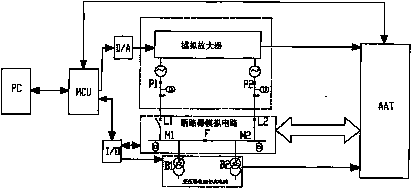
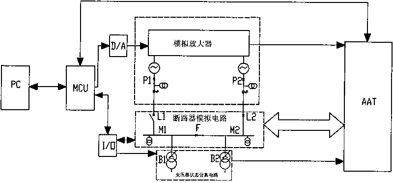
[0015] The present invention as figure 1 As shown, it is connected with the self-injection device of the tested equipment, including a host computer and a lower computer, which also includes an analog amplifier, a circuit breaker simulation circuit, and a transformer state simulation circuit, and the lower computer is connected to the analog amplifier through a digital-to-analog converter; The lower computer is connected to the circuit breaker simulation circuit and the transformer state simulation circuit through I / O; the lower computer and the circuit breaker simulation circuit are provided with a data interface for two-way exchange with the self-injection device of the tested equipment; the analog amplifier is provided with Connect the voltage and current output port of the self-injection device of the tested equipment, and the P1 and P2 output ports connected to the circuit breaker analog circuit; the transformer state simulation circuit is provided with an interface for on...


PUM


Abstract

The invention discloses a spare automatic switching comprehensive tester, and relates to a comprehensive tester of a spare automatic switching device in the field of an electrical power system and a power supply system. The spare automatic switching comprehensive tester can simulate a primary system operation state and a main transformation fault state and implement state detection on a detected spare automatic switching device comprehensively and intuitively on the premise of meeting the requirements of the prior art, and comprises an upper computer, a lower computer, an analogue amplifier, a circuit-breaker analogue circuit and a transformer state simulation circuit. The lower computer is connected with the analogue amplifier through a digital-to-analog converter and is connected with the circuit-breaker analogue circuit and the transformer state simulation circuit; the lower computer and the circuit-breaker analogue circuit are provided with a data interface which exchanges data with the detected spare automatic switching device bidirectionally; the analogue amplifier is provided with a voltage / current output port connected with the detected spare automatic switching device, and output ports P1 and P2 connected with the circuit-breaker analogue circuit; and the transformer state simulation circuit is provided with an interface through which a transformer state signal is transmitted to the detected spare automatic switching device unidirectionally, and output ports B1 and B2 connected with the circuit-breaker analogue circuit.

Description

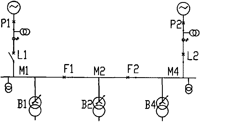
technical field [0001] The invention relates to the field of electric power system power supply systems, and is particularly suitable for comprehensive testing of substations and important users with dual or multiple power sources as standby self-injection devices for mutual backup power supply. Background technique [0002] In the process of power production and supply, in order to ensure the reliability of power supply and minimize power outages to users, substations and important users generally adopt dual power sources or multiple power sources as backup power sources for each other. The switch device") is an intelligent control device that realizes this function, and its safe and reliable operation is the key to ensure the success of the power backup switch. [0003] According to statistics, the blackout accidents caused by the refusal and malfunction of the standby automatic switching device itself still account for a considerable proportion of the power system blackou...

Claims


Application Information

Patent Timeline
IPC IPC(8): G01R31/00
Inventor 王友
Owner JIANGSU ELECTRIC POWER COMPANY YANGZHOU POWER
Learn More