
Ant-theft alarm

A technology of anti-theft alarm and alarm circuit, which is applied in the field of alarms, and achieves the effects of novel and reasonable conception, convenient use, and solution to anti-theft alarms

Inactive Publication Date: 2013-05-01
PUYANG POWER SUPPLY COMPANY STATE GRID HENAN ELECTRIC POWER
View PDF6 Cites 0 Cited by
  • Summary
  • Abstract
  • Description
  • Claims
  • Application Information

AI Technical Summary

Problems solved by technology

[0002]With the popularization of the power grid, the phenomenon of transformers being stolen by criminals is becoming more and more rampant, causing great losses to the national economy. The theft is mainly manifested in transformers. load consumption, the transformer is usually cut off, and there is no special person to take care of it, so there is an opportunity for thieves to take advantage of. In order to solve this problem, people have adopted many methods, such as: building a small house, locking the transformer and other equipment, Due to the large number of houses built and the high cost, it is difficult to promote; or the establishment of mobile substations has disadvantages such as high cost, inconvenient use, and unsafety; currently there are also anti-theft alarm devices installed on transformers, but The alarms currently used in the market are all under the condition that the 10 kV line and the transformer are charged to prevent theft of the transformer and the line.
When the transformer is out of power, in order to realize the anti-theft of 10 kV line, patent No. 2003201134119 has developed an anti-theft device, but this kind of alarm can only disconnect the two-phase high voltage of A and C, and the high voltage of phase B must be kept to prevent the transformer and B If the phase line is stolen, it cannot prevent the A and C phase high-voltage lines from being stolen

Method used


Image

  • Ant-theft alarm
  • Ant-theft alarm

Examples


Embodiment 1

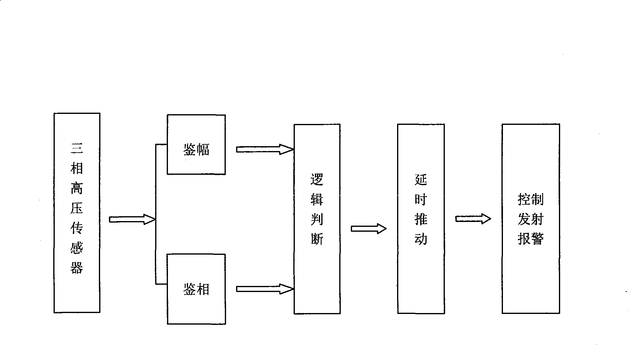
[0016] Such as figure 1 As shown, the present invention respectively arranges high-voltage sensors in the three-phase circuits of high-voltage electric wires, and each sensor collects the signals in the phase circuits, and sends the signals in the phase circuits to the demodulation circuit, and the signal output by the demodulation circuit Send to the logic judgment circuit, the logic judgment circuit is connected with the control emission alarm circuit, and the control emission alarm circuit outputs the control signal to the alarm, so if any phase in the circuit is disconnected, the control emission alarm circuit outputs the control signal to the alarm , The alarm sends out an alarm, effectively preventing theft of transformers and lines. The above-mentioned demodulation circuit is composed of an amplitude detector circuit and a phase detector circuit, and an overvoltage detection circuit and an overvoltage detection circuit are also provided at the output end of the demodul...

Embodiment 2

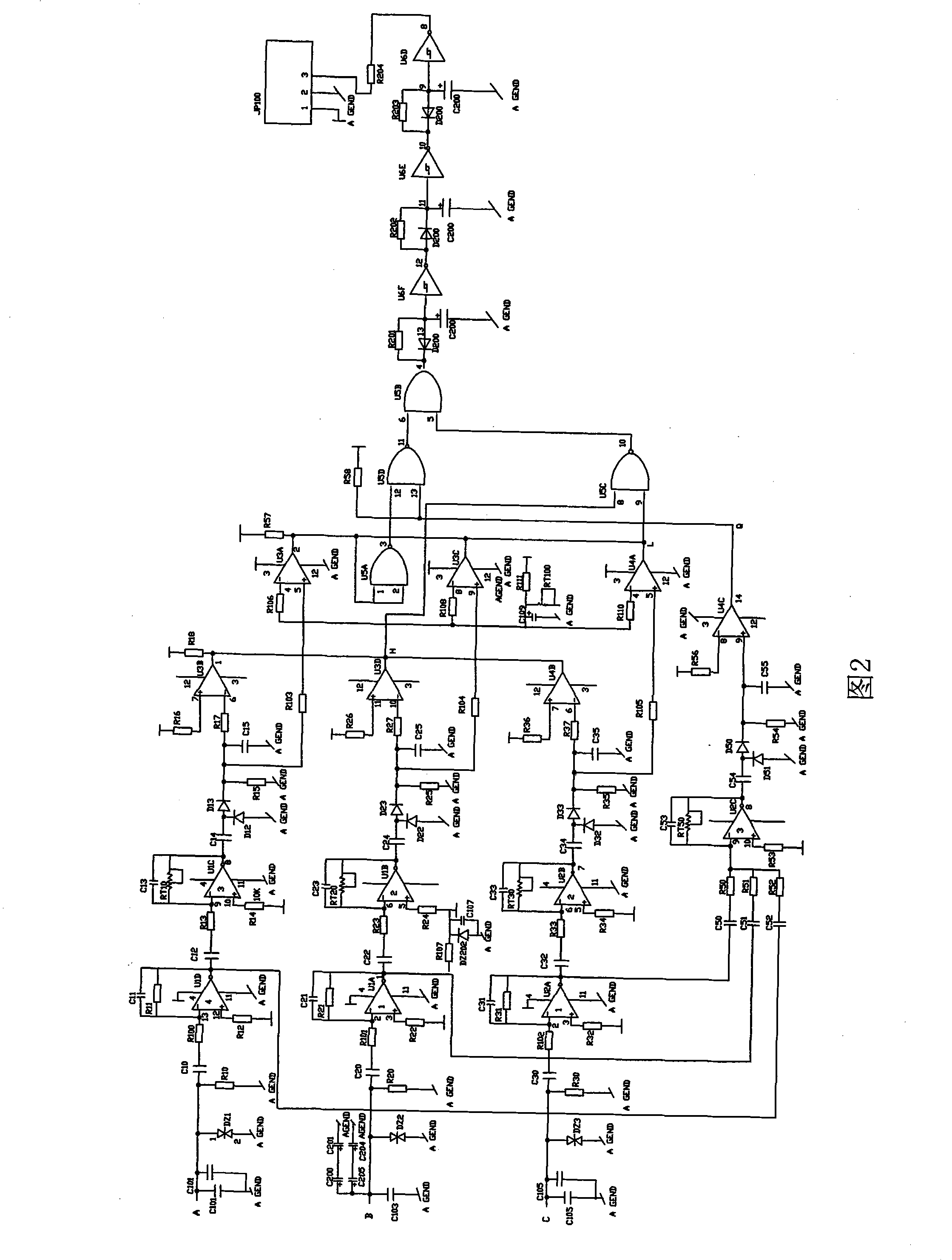
[0042] In this embodiment, different from Embodiment 1, the logic judgment circuit is connected with the control emission alarm circuit through the delay push circuit. The signal passes through the delay driving circuit composed of three inverting operational amplifier circuits U6F, U6E and U6D in sequence, and then is transmitted to the control emission alarm circuit. This can effectively prevent instantaneous interference, avoid the triggering effect of the clutter signal on the control emission alarm circuit, and provide a guarantee for the normal operation of the present invention.

[0043] Other technical characteristics and working process are identical with embodiment 1.

Embodiment 3

[0045] In this embodiment, different from Embodiment 1, the alarm is connected to the solar panel, so that the power required by the alarm is usually provided by the solar panel. The above solar panel technology is well known to those skilled in the art.

[0046] Other technical characteristics and working process are identical with embodiment 1.


PUM


Abstract

The invention discloses an anti-theft alarm. Sensors are arranged in three-phase circuits of a high-voltage line respectively, wherein each sensor is connected with the input end of a demodulator circuit; the output end of the demodulator circuit is connected with the input end of a logical judgment circuit; the output end of the logical judgment circuit is connected with the input end of a control transmission alarm circuit; and the output end of the control transmission alarm circuit is connected with an alarm. The anti-theft alarm performs logical judgment on a demodulated signal and if any phase is cut off, controls the control transmission alarm circuit to output a control signal to the alarm, so that the alarm gives an alarm message to effectively guard the transformer and the line against thefts. The entire transformer may be powered off without no-load loss in the invention. When the anti-theft alarm is arranged for use, the three high-voltage sensors may be arranged on a falling type safety cross arm in the circuit so as to be connected with the alarm. The anti-theft alarm is characterized by novel, rational conception and low cost and can effectively solve the problem ofgiving anti-theft alarm upon power consumption without no-load loss.

Description

technical field [0001] The invention relates to an alarm, in particular to an alarm for preventing transformers and their lines from being stolen. Background technique [0002] With the popularization of the power grid, the phenomenon of some criminals stealing transformers is becoming more and more rampant, causing great losses to the national economy. The theft is mainly manifested in the transformer. Leaving an opportunity for thieves, in order to solve this problem, people have adopted many methods, such as: building a small house and locking up transformers and other equipment. Because the number of houses is large and the cost is high, it is difficult to promotion; or the establishment of mobile substations, there are disadvantages such as high cost, inconvenient use, and unsafety; currently, there are also anti-theft alarm devices installed on transformers, but the alarms currently used in the market are all on 10 kV lines When the transformer is charged, the transf...

Claims


Application Information

Patent Timeline
Patent Type & Authority Patents(China)
IPC IPC(8): G08B13/00G01R31/02
Inventor 李锋茹王广川陈玉胜赵国安王勇胥鸣秦文韬
Owner PUYANG POWER SUPPLY COMPANY STATE GRID HENAN ELECTRIC POWER
Learn More