Long-travel high-accuracy multiple-degree-of-freedom planar motor

A plane motor, long stroke technology, applied in electrical components, electromechanical devices, electric components, etc., can solve the problems of limited mover stroke, complex control, low positioning accuracy, etc., and achieve the effect of high degree of freedom and high precision

Active Publication Date: 2010-06-23
HARBIN INST OF TECH
View PDF0 Cites 15 Cited by
  • Summary
  • Abstract
  • Description
  • Claims
  • Application Information

AI Technical Summary

Problems solved by technology

[0005] In order to solve the problems of limited stroke, complex control and low positioning accuracy of the exi...

Method used


Image

  • Long-travel high-accuracy multiple-degree-of-freedom planar motor
  • Long-travel high-accuracy multiple-degree-of-freedom planar motor
  • Long-travel high-accuracy multiple-degree-of-freedom planar motor

Examples


specific Embodiment approach 1

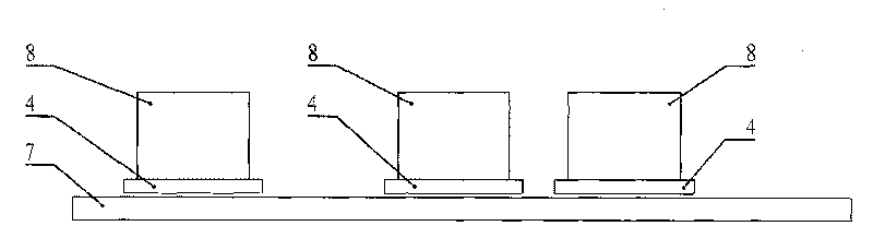
[0009] Specific implementation mode one: see figure 1 This embodiment will be described. The long-stroke high-precision multi-degree-of-freedom planar motor described in this embodiment includes a stator 7 of a long-stroke planar motor, i movers 4 of a long-stroke planar motor and i short-stroke multi-degree-of-freedom magnetic levitation planar motors 8, A short-stroke multi-degree-of-freedom magnetic levitation planar motor 8 is fixed on the mover 4 of each long-stroke planar motor, and each short-stroke multi-degree-of-freedom magnetic levitation planar motor 8 is composed of a short-stroke planar motor and a magnetic levitation support device. The magnetic levitation support device includes m magnetic levitation support mechanisms, the stator of the short-stroke planar motor is fixedly connected to the mover of the long-stroke planar motor, and the m magnetic levitation support mechanisms are all distributed around the stator of the short-stroke planar motor, and The sta...

specific Embodiment approach 2

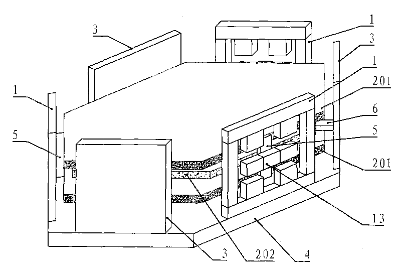
[0011] Embodiment 2: The difference between this embodiment and the long-stroke, high-precision, multi-degree-of-freedom planar motor described in Embodiment 1 is that the m is 3, that is, each set of magnetic levitation support mechanisms is composed of three magnetic levitation support mechanisms 1, so The three magnetic levitation support mechanisms 1 are 120° apart from each other.

specific Embodiment approach 3

[0012] Embodiment 3: This embodiment is an embodiment of the short-stroke multi-degree-of-freedom magnetic levitation planar motor 8 described in Embodiment 2. see figure 2 As shown, the short-stroke planar motor 2 in the figure is a regular hexagonal bilateral structure with a symmetrical structure, and the permanent magnet excitation component arrays on both sides are movers 202, and the middle armature component is a stator 201, of which three The magnetic levitation support mechanisms 1 are fixed on the upper surface of the base plate 4 at 120° to each other, and the three support frames 3 are fixed on the upper surface of the base plate 4 at 120° to each other, and the three magnetic levitation support mechanisms 1 and the three support Frames 3 are arranged alternately to form a regular hexagon with a symmetrical structure. The short-stroke planar motor is located in a regular hexagon with a symmetrical structure surrounded by three magnetic levitation support mechanism...


PUM


Abstract

The invention relates to a long-travel high-accuracy multiple-degree-of-freedom planar motor which belongs to the field of motors. The planar motor solves the problems that the traditional planar motors have the defects of limited travel of rotors, complex control, low positioning accuracy and the like. The planar motor comprises a stator of the long-travel planar motor, i rotors of the long-travel planar motor, i short-travel planar motors and i sets of magnetic levitation supporting device, wherein one short-travel planar motor and one magnetic levitation supporting device are fixed on each rotor of the long-travel planar motor; each magnetic levitation supporting device comprises m magnetic levitation support mechanisms, and the m magnetic levitation support mechanisms are evenly distributed to the periphery of the stator of the short-travel planar motor; the stator of the short-travel planar motor is fixedly connected with the rotor of the long-travel planar motor and stators of the m magnetic levitation support mechanisms, and all rotors of the m magnetic levitation support mechanisms are fixedly connected with a rotor of the short-travel planar motor; i is an integer greater than 0, and m is an integer greater than 1.

Description

technical field [0001] The invention belongs to the field of motors, in particular to a long-stroke, high-precision, multi-degree-of-freedom planar motor. Background technique [0002] Modern precision and ultra-precision processing equipment has an urgent need for high-response, high-speed, high-precision planar drive devices, such as machining, electronic product production, mechanical loading and unloading, manufacturing automated instrumentation equipment, and even robot drives. Usually these devices are powered by a rotary motor, and then converted into linear motion by mechanical devices such as belts and ball screws. Due to the complexity of the mechanical device, the transmission accuracy and speed are limited, and frequent adjustments are required, resulting in high cost, poor reliability, and large volume. The original planar driving device was realized by two directly driven linear motors, and a stacked driving structure was adopted. This structure increased the ...

Claims


Application Information

Patent Timeline
IPC IPC(8): H02K41/03
Inventor 寇宝泉张千帆程树康
Owner HARBIN INST OF TECH
Why Eureka
Try Eureka